Heating element and air channel installation, Ducting, Important – Steffes 3120 Simplified Installation Guide User Manual
Page 2: Warning
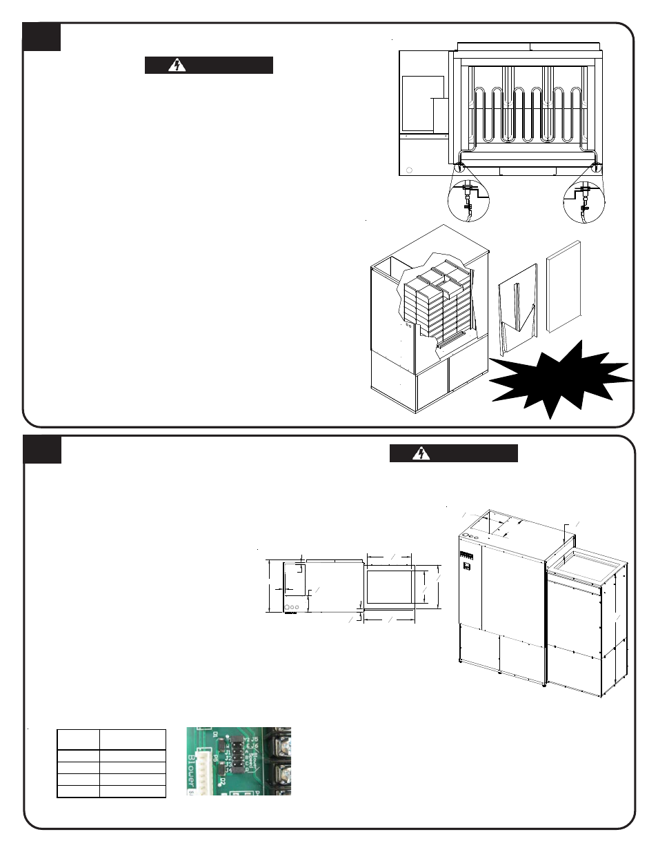
HEATING ELEMENT AND AIR CHANNEL INSTALLATION
4
WARNING
WARNING
WARNING
WARNING
WARNING
HAZARDOUS VOLTAGE: Risk of electric shock. Can cause
injury or death.
DO NOT remove electrical panel cover while system is ener-
gized.
Elements MUST be positioned properly to avoid short circuit-
ing them against any surfaces within system.
Use care when making connections to avoid element dam-
age.
1. Insert heating elements between brick layers until element ends
embed into side cutouts of brick cavity. The threaded screw tabs on
wire connection terminals should point forward.
2. Install air channel with air deflectors (arrow shaped pieces) facing
inward and narrow ends of deflectors pointing up. Place top of air
channel in first.
3. Lower insulation blankets back into position, one at a time. Tuck
sides into edges, corners and around exposed portions of heating
elements.
4. Install galvanized panel. Slide the top inside the upper lip of top
painted panel. Bottom rests on the outside of the brick cavity.
5. Connect wiring harnesses to heating elements using screws in
element screw kit. Install screws with heads up and threads pointing
down. Tighten screws to 14 in·lbs.
6. Check non-insulated element connections to make sure they do not
come within 1/2" of any surface.
7. Install painted front panel.
DUCTING
5
1. Assemble factory supplied return air plenum
per the instructions provided with the plenum.
2. Once assembled, set plenum on right side of
the system with air filter and indoor coil access
covers facing forward. Line up predrilled holes
on system with holes in flanges of plenum and
attach using screws provided in plenums
hardware package.
NOTE: The 3100 series is factory config-
ured for a right-to-left airflow.
3. Insert air filter into filter rack.
4. Connect return air duct to top of plenum.
5. Connect supply air duct in structure directly to
systems air outlet.
6. If necessary, adjust supply air blower speed by
using the chart below.
7. The W/E jumper MUST be in the ON position or
the blower will not operate with an E call from
the thermostat.
When interfacing with a heat pump, the A-Coil MUST
be placed on the return air side.
To maintain a room temperature of 85
o
F or less in the
mechanical room, a 24" x 24" opening can be in-
stalled in the area or a 6" x 6" non-closing register
can be cut into the return air duct. Refer to Place-
ment and Clearance Requirements section of
Owners and Installers Manual for more information.
10
1
8
"
53
5
8
"
16"
5
3
8
"
HAZARDOUS VOLTAGE: Risk of electric shock. Can cause injury
or death. DO NOT operate the Comfort Plus heating system
without ducting installed to both the air inlet and outlet.
WARNING
WARNING
WARNING
WARNING
WARNING
Fr
on
t A
ir C
ha
nn
el
Fr
on
t
Br
ick
Sid
e
Bo
tto
m
IMPORTANT
System
Top of
27"
1"
812"
1"
22516"
16716"
2618"
17 8"
22716"
External static pressure should not exceed .75 inches water column.
Element-to-Wiring
Harness Connections
Jumper
½ HP Variable
Speed CFM
A 1000
B 1200
C 1400
D 1600