Configuration menu – Steffes 2106 Simplified Installation Guide User Manual
Page 4
7
CONFIGURATION MENU
The Steffes 2100 Series room heating units have a Configuration
Menu, which allows the heaters to be customized to the power
company and consumer’s needs. This menu can be accessed on
start-up and allows configuration settings to be easily adjusted.
Accessing the Configuration Menu
Step 1
Energize the heater. Access to the Configuration Menu is
allowed for the first two (2) minutes of operation. If the
heater has been energized for over two (2) minutes, it
must be powered off and back on again.
Step 2
Press and release the
M button until the faceplate
displays “CONF.”
Step 3
Press the up arrow once and the faceplate will display
“C000.” The display will flash between “C000” and the
corresponding configuration value.
3050 Hwy 22 North
Dickinson, ND 58601-9413
701-483-5400
www.steffes.com
“Manufactured in North America”
Part No. 1200286-4
R
R
If access to Configuration Menu times out, the
system must be powered off at the circuit
breaker and back on to re-enter the menu.
Step 4
If necessary, edit the configuration by pressing
and holding the
M button while using the up or
the down arrow button to change the value.
Step 5
Once the value is correct, release the buttons and
press the up arrow button to go to the next
configuration (C001, C002, etc.).
Step 6
Repeat steps 4 through 5 until all configuration
settings have been adjusted to the desired values.
Step 7
Once configured, use the down arrow to leave the
Configuration Menu.
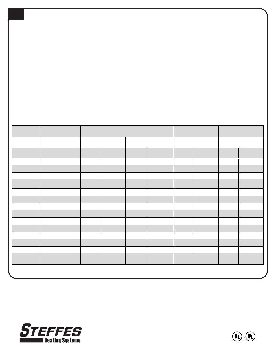
In most applications only a few, if any, configuration changes will be necessary. Following is a description of the
configuration settings and their functions:
Power Line Carrier
(PLC) Peak Control *
Low Voltage Direct Wired Peak Control
Time Clock Module
Peak Control
Line Voltage Peak
Control
Peak Switch Closed for
Charging
Peak Switch Open for
Charging
Configuration
Number
Outdoor
Sensor
No Outdoor
Sensor
Outdoor
Sensor
No Outdoor
Sensor
Outdoor
Sensor
No Outdoor
Sensor
Outdoor
Sensor
No Outdoor
Sensor
C000
5
5 6 5 6 5 6 5 6
C001
60°F
60°F
60°F
60°F
60°F
60°F
60°F
60°F
60°F
C002
20°F
20°F
20°F
20°F
20°F
20°F
20°F
20°F
20°F
C003
Match to the Channel
Selected at PLC
0
0
0
0
0
0
0
0
C004
154
155 154 155 154 159 158 155 154
C005
0
1
1
0
0
0
0
0
0
C006
6
6 6 6 6 6 6 6 6
C007
30
30
30
30
30
30
30
30
30
C008
5°F
5°F
5°F
5°F
5°F
5°F
5°F
5°F
5°F
C009
5°F
5°F
5°F
5°F
5°F
5°F
5°F
5°F
5°F
C010
90°F
90°F
90°F
90°F
90°F
90°F
90°F
90°F
90°F
C011
70°F
70°F
70°F
70°F
70°F
70°F
70°F
70°F
70°F
C012
60°F
60°F
60°F
60°F
60°F
60°F
60°F
60°F
60°F
C013 - C021
Refer to the Time Clock
Installation Instructions
*Factory Default is Power Line Carrier (PLC) Peak Control using Channel 3