Low voltage connections for direct wired controls, Brick loading – Steffes 2106 Simplified Installation Guide User Manual
Page 3
5
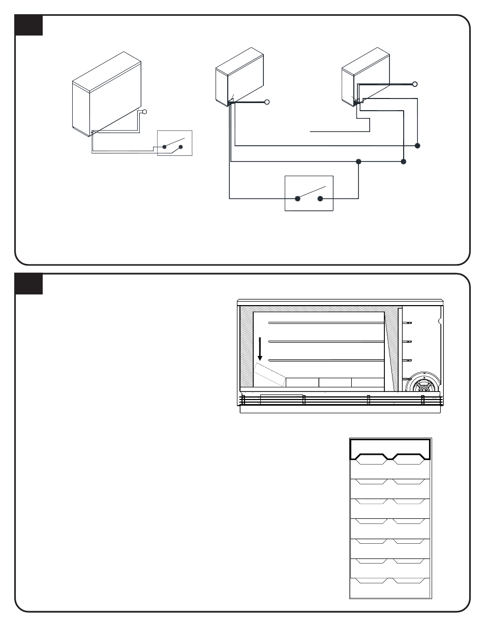
LOW VOLTAGE CONNECTIONS FOR DIRECT WIRED CONTROLS
NOTES
1.
If using power line carrier (PLC) controls, a Steffes
Time Clock Module, or line voltage for peak control,
refer to the Owner’s and Installer’s Manual for
installation instructions. Then, skip to Section 6 to
complete the installation.
2.
Connecting the low voltage hot (blue) wire from multiple heaters to a single control switch may cause damage to the system.
In multiple heater applications, connect the wires as shown for proper operation.
3.
In multiple heater applications, one outdoor sensor is needed for each heater installed.
4.
If routing low voltage wire near line voltage conductors, shielded wire must be used.
SINGLE HEATER
MULTIPLE HEATERS
6
BRICK LOADING
1.
Verify that the heater is not energized.
2.
Place the heater against the wall support bracket. Use the carriage bolts to secure
the heater to the wall.
3.
Place shipping box in front of the heater for ease in cleanup of brick debris.
4.
Remove the screws on the right side of the galvanized front panel. Rotate the panel
to the left to remove.
5.
Model 2104, 2105, or 2106 - remove and discard the cardboard spacer(s) from the
brick core.
6.
Install the first brick faceup and slide to the far right side of the heater’s storage
cavity. Be sure the grooved side of the brick is up and fits tight against the right air
channel and the back insulation panel. Continue loading the bricks for Row 1. The
insulation on the left side may need to be compressed to install the last brick on
each row.
7.
All bricks in rows one through seven must be loaded with the grooved side up.
8.
Using the brick installation tool provided, install the eighth (top) row of bricks with
the grooved side of the bricks facing down.
9.
Reinstall the galvanized front panel.
• The heater MUST be securely mounted to
the wall prior to brick loading.
• Install bricks carefully to avoid damage to
the bottom and back insulation panels of
the storage cavity.
• Maintain an even horizontal line across the
brick core during brick installation so air
flow through the heater is not obstructed.
• To properly seal the brick core, make sure
all bricks are installed correctly.
Note: Row 8 brick faces down
Row 7
Row 6
Row 5
Row 4
Row 3
Row 2
Row 1
SIDE VIEW
Control Switch
Peak
Outdoor Sensor
Gray
Gray
Blue/White
Blue
BACK OF
HEATER
4
3
2
1
BA
CK
O
F H
EA
TE
R
Blue/White (Peak)
Blue (Hot)
Black (Common)
Blue (Not Used)
BA
CK
O
F H
EA
TE
R
Blue/White
Outdoor Sensor
Black
#2
#1
Gray
Gray
Gray
Gray
Peak Control Switch
Outdoor Sensor
(See Note 3)
(See Note 2)
(See Note 3)
Low Voltage
Junction Box
Low
Voltage
Junction
Box