O power switch, O range switch, Ohpf switch (q2031b) – Yamaha Graphic Equaliser Q2031B User Manual
Page 5: Switch (gq1031c/gq2015a), O eq switch, 0 level control, 0hpf control (q2031b), Front panel o, Power switch, Eq switch
Attention! The text in this document has been recognized automatically. To view the original document, you can use the "Original mode".
FRONT PANEL
O
POWER switch
When this switch is pressed to turn the power on, the POWER
indicator LED above the switch will light.
* To prevent click noise, the output is muted for approximately
two seconds after the power is turned on.
O RANGE switch
Allows selection of the boost or cut range for equalization.
When this switch is off, the maximum range of +/-12 dB is
selected; when on, the +/-6 dB range is selected. Use this
switch to select the range suitable for each application. When
the switch is on, the LED indicator to its left lights to show
that the +/-6 dB range is in effect.
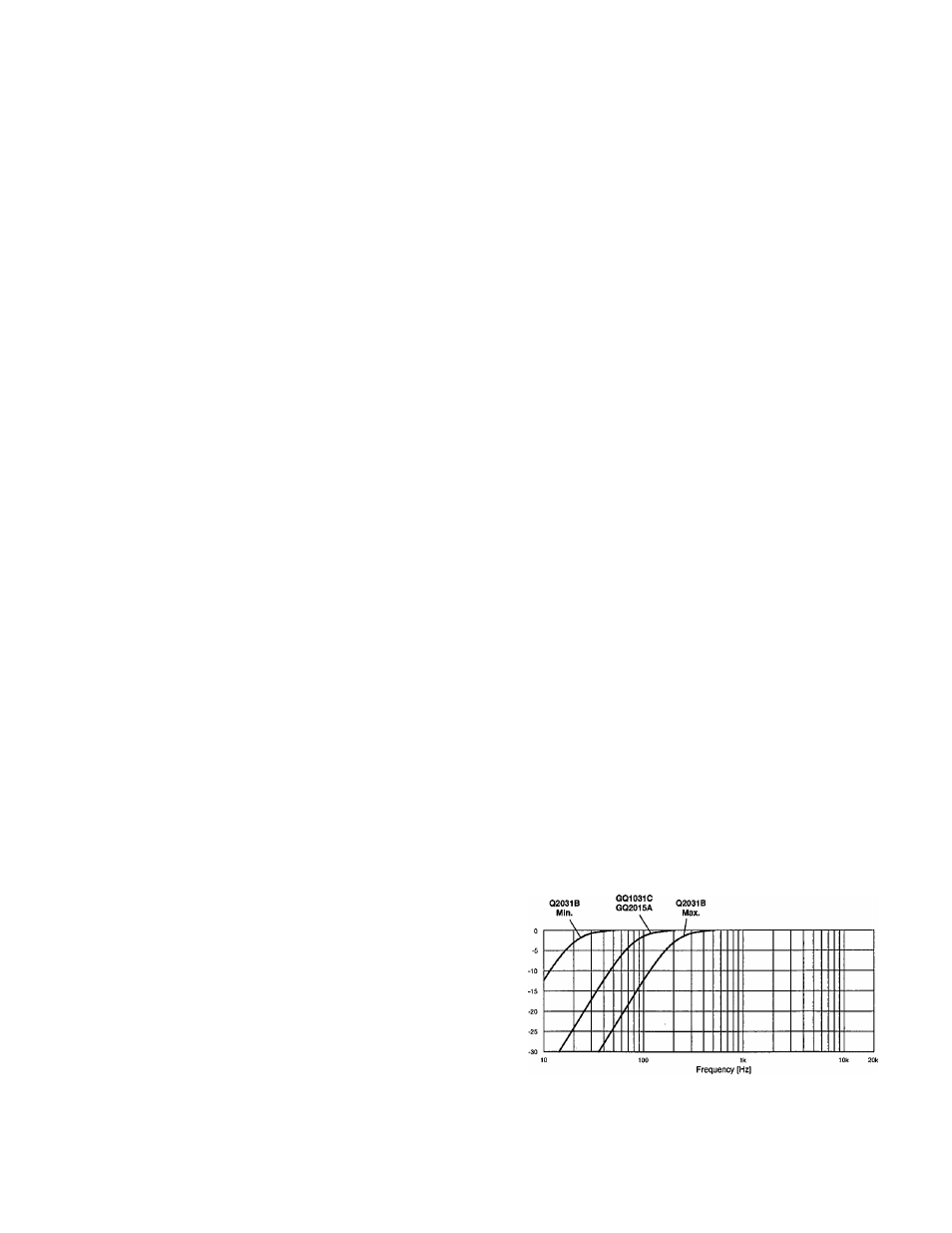
OHPF switch (Q2031B)
/^switch (GQ1031C/GQ2015A)
Allows switching the high pass filter in or out of the audio
path. When the switch is on, the high pass filter is effective
and the indicator LED lights. The Q2031B provides 12 dB
per octave rolloff below the frequency set with the HPF con
trol
0,
while on the GQ1031C/GQ2015A the rolloff is 12 dB
per cotave below 80 Hz.
When the switch is off, the input signal goes directly to the
equalizer section, bypassing the HPF.
On the GQ2015Athe /80 switch turns the HPF on/off for
channels A and B simultaneously.
O
EQ switch
This switch determines whether the signal is routed through
or bypasses the equalizer section. When the switch is off,
the equalizer is bypassed and the settings of the equalizer
controls O are ineffective, providing a flat frequency re
sponse. When the switch is on, its indicator lights and the
equalizer is switched into the audio path. The equalized sig
nal can be compared with the un-equalized signal simply by
alternately turning the EQ switch on and off.
0
LEVEL control
Allows precise control of the optimum input sensitivity. When
the control is at the top of the scale, the input level remains
unchanged (+4 dB).
This control can be used to restore the output level when the
overall level has been changed during the equalization pro
cess. This, however, will also change the input level. Equal
ization methods which do not change the LEVEL control set
ting will yield a better signal-to-noise ratio and wider dynamic
range.
Example:
The settings in Fig. A will provide a better result
than the settings in Fig. B.
• Boost/cut settings centered around the 0 dB point
ffWI
E3E
Fig. A
• Boost/cut settings off the 0 dB point
e
3
e
3
e
:
e
3 E ;
e
I
e
3
e
3
e
: =
z i E g = : = : = i z 3 z : z 3 z 3 E : E : E 3 z : = 3
Fig. B
0HPF control (Q2031B)
The HPF control sets the rolloff frequency for the built-in high
pass filter. The control allows continuous adjustment over
the range of 20 Hz to 200 Hz. Below the selected frequency
there will be a 12 dB per octave cut.
The filter is turned on/off using the HPF switch
0.
The HPF can be adjusted to eliminate low-range standing
waves, a resonance phenomenon that sometimes occurs in
small indoor environments, vocal "pops" and wind noise in
microphones and AC hum.