Adjustments – Panasonic WV-7230D User Manual
Page 9
Attention! The text in this document has been recognized automatically. To view the original document, you can use the "Original mode".
Zoom Control Connector
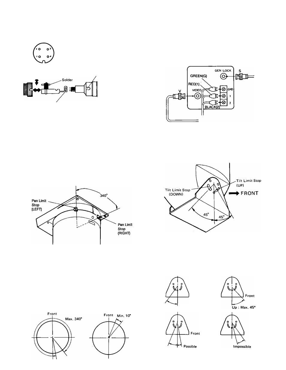
The control connector of the motorized zoom lens should
be a 4- pin connector, Hirschman type Mas 4100. If it is
not, substitute the existing connector with the Mas 4100
supplied, according to the following diagram:
1. DC COM
2. IRIS
3. FOCUS
4. ZOOM
Push here for removing
Case
rv
Lens Control
Cable
Motorized
Zoom Lens
Clamp
Camera Power Cable
Connect the spade lug connectors to the 24V AC Power
Terminal Strip of the lowvoltage camera, according to the
diagram.
Camera Cable
Connect the Camera Cable to the video output connector
of the lowvoltage camera.
CAMERA
ADJUSTMENTS
CAUTION:
The following adjustments should be made by qualified
service personnel or system installers.
After the cable is assembled and the unit Is connected, plug
the Remote Control Unit into a 120V AC source and proceed
as follows.
A. Panning Angle
3.
4.
Loosen the Pan Limit Stops.
Press on the ON/OFF Switch ON to energize the unit,
then rotate Pan/Tilt Head using the joystick Pan/Tilt
Control unit the desired right pan limit is reached.
Locate the right pan limit stop and move until it
contacts limit switch inside the Pan/Tilt Head. Move
stop additional slight amount until a 'clock” is heard
indicating opening of limit switch. Lock the stop in
place.
Rotate the Pan/tilt Head to the desired left limit position.
Adjust the left pan limit stop as was done for the right
limit stop.
5.
With both limit stops in place, pan to both stop positions
and recheck for exact positioning of limit stops, tighten
both stops securely.
B. Tilting Angle
Loosen the recessed two Tilt Limit Stops and rotate
Pan/Tilt Control until desired upward limit is reached.
Move the upward limit stop toward the bottom of the
slot until a "clock" can be heard. Tighten screw.
Adjust the downward limit stop the same way.
Lock the limit stops securely inplace after checking for
exact positioning.
Front
Down : Max. 45*
- 8 -