Voltage, Current, Voltage -15 – Dynon Avionics FlightDEK-D180 Installation Guide User Manual
Page 73: Current -15
EMS
Configuration
Voltage
The voltmeter info item reports the voltage that the FlightDEK-D180 reads on its Master Power
input (pin 1 on the EFIS 25-pin connector). Because of this, there is no sensor to install or
configure. Simply, select the alarm mode and the analog bar thresholds as described in Alarm
and Color Threshold Configuration on page 6-2. Configure the voltmeter info bar to display in
the desired location(s), as described in the FlightDEK-D180 Pilot’s User Guide > Global
Configuration Settings > Info Item Configuration section.
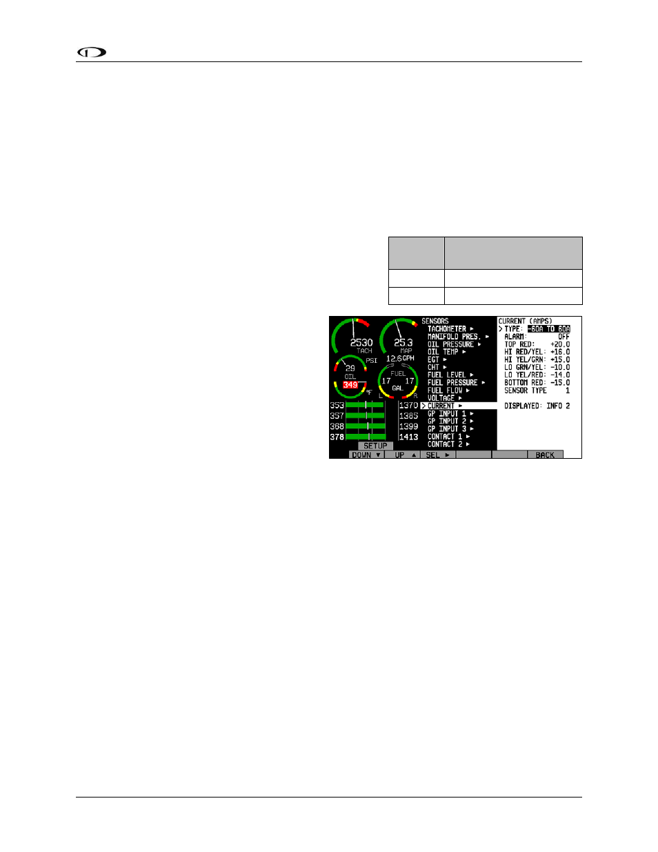
Current
If a current sensor has been installed, set the DISPLAY
parameter to ON, otherwise, set it to OFF. First, select
whether your ammeter will be showing positive and
negative currents (-60A TO 60A; used for Location A)
or only positive currents (0A TO 60A; used for
Locations B and C). This will depend on your
installation as mentioned in the Ammeter
Shunt installation section on page 3-12. Select
the alarm mode and the analog bar thresholds
as described in Alarm and Color Threshold
Configuration on page 6-2. Change the
SENSOR TYPE to the correct number using
the sensor type table. Configure the ammeter
info bar to display in the desired location(s),
as described in the FlightDEK-D180 Pilot’s
User Guide > Global Configuration Settings >
Info Item Configuration section.
Sensor
Type
Ammeter Sensor
1 Dynon
P/N
100412-000
2 GRT
CS-01
If you are using the GRT CS-01 Hall effect sensor, you may need to set the zero-point of the
sensor. After you have selected a SENSOR TYPE of “2,” the OFFSET parameter will be
displayed. Adjust the OFFSET (in increments of 1 amp) until the current displayed on the EMS
Main page screen is correct at a known current.
FlightDEK-D180 Installation Guide
6-15