Model 1020 standalone enclosure user manual – CANOGA PERKINS 1020 Standalone Enclosure User Manual
Page 3
EdgeAccess Model 1020
3
Model 1020 Standalone Enclosure User Manual
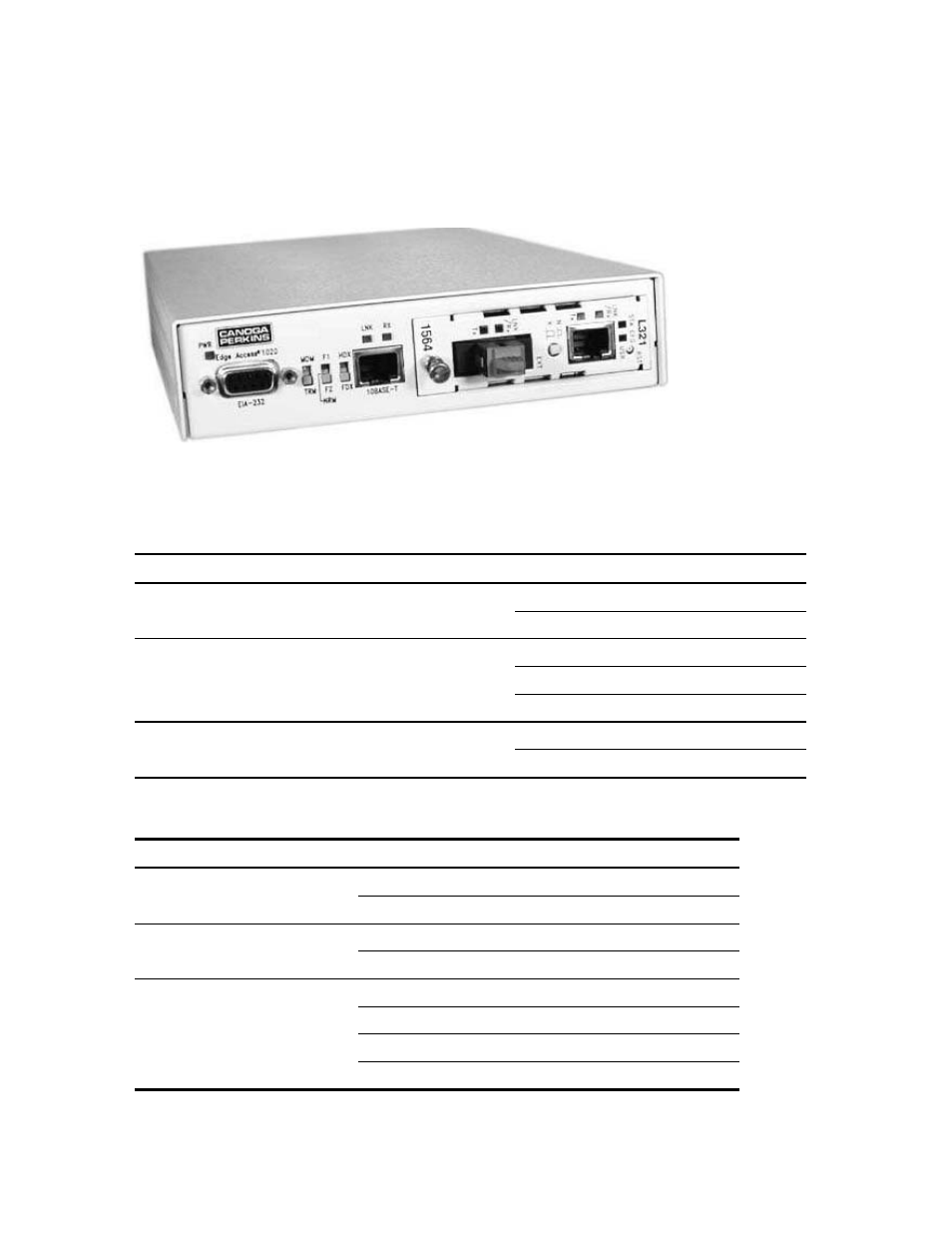
The Model 1020 standalone enclosure, shown in Figure 1, supports one 2U-sized module that is
managed through either SNMP or Sideband Management Control (SBMC).
Figure 1. Model 1020 Standalone Enclosure
The front provides three switches, three LEDs, two connectors, and a slot for a managed module. The
back includes an AC power cord socket. The AC power supply provides +5 VDC to the module.
Switch
Setting
Selects
MDM/TRM for EIA-232 port
MDM
DTE terminal for SLIP
TRM
DCE terminal for VT100
F1/NRM/F2, typically for Loopback for the module
F1
Local loopback, typically
Note: Set to NRM except to isolate a fault.
NRM
Normal operation
F2
Remote loopback, typically
HDX/FDX for 10BASE-T port
HDX
Half duplex
FDX
Full duplex
Note: If the link partner is set to auto-negotiation, the link uses 10M and follows the HDX/FDX
switch setting for this port; otherwise, set this switch to match the other switch on the link.
LED
State
Definition
PWR
Off
No power
Green
Power is on
Tx for 10BASE-T port
Off
No transmission
Green blinking
Transmission activity
LNK/Rx for 10BASE-T port
Off
No link
Green
Link is established at full duplex
Amber
Link is established at half duplex
Blinking
Data is received