Model 1040 standalone enclosure user manual – CANOGA PERKINS 1040 Standalone Enclosure User Manual
Page 3
EdgeAccess Model 1040
3
Model 1040 Standalone Enclosure User Manual
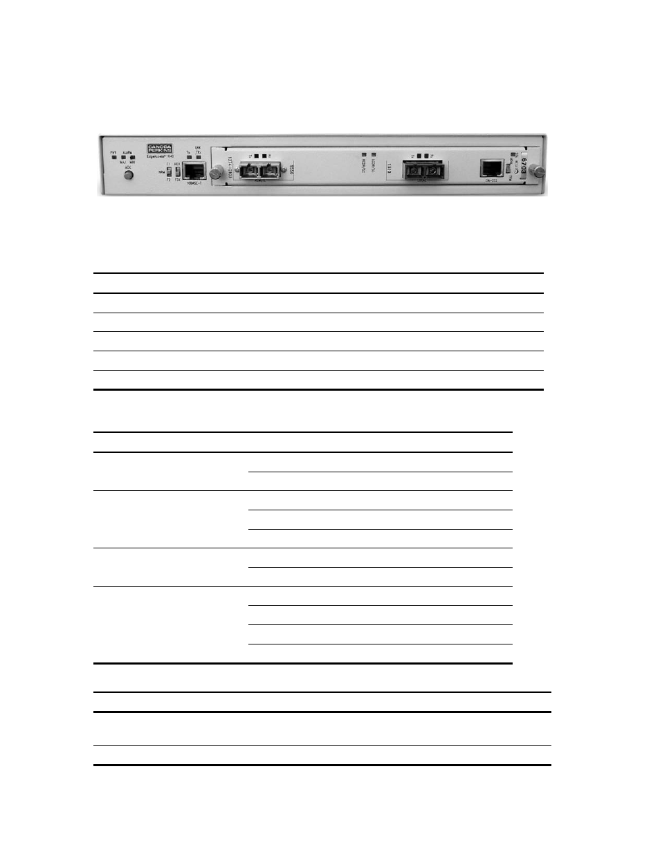
The Model 1040 standalone enclosure, shown in Figure 1, supports one 5U-sized managed module.
Figure 1. Model 1040 Standalone Enclosure
The front provides two switches, five LEDs, one connector, and a slot for a module. The back
includes an AC power cord socket and the ALM IN and ALM OUT connectors.
Switch Setting
Selects
F1/NRM/F2 for the module
F1
Function 1, such as Local loopback
NRM
Normal operation; set this for most applications
F2
Function 2, such as Remote loopback
HDX/FDX for 10BASE-T port
HDX
Half duplex
FDX
Full
duplex
Note: If the link partner is set to auto-negotiation, the link uses 10M and follows the HDX/FDX
switch setting for this port; otherwise, set this switch to match the other switch on the link.
LED State
Definition
PWR Off
No
power
Green
Power is on
ALARM, MAJ and MIN
Off
Normal
MIN
Amber
Minor
alarm
MAJ
Red
Major
alarm
Tx for 10BASE-T port
Off
No transmission
Green blinking
Transmission activity
LNK/Rx for 10BASE-T port
Off
No link
Green
Link is established at full duplex
Amber
Link is established at half duplex
Blinking
Data is received
Note: To clear a latched Minor or Major alarm, push the ACK button.
Connector Provides
ALM IN and ALM OUT, MIN and MAJ
Alarm status from another device (IN) and to
another device (OUT)
10BASE-T
Half or full duplex Ethernet