Iv. adjustment instructions – Beckett SQM40 User Manual
Page 3
3
CG15 / CG25 / CG50 Optional Modulation Control Systems
Figure 5
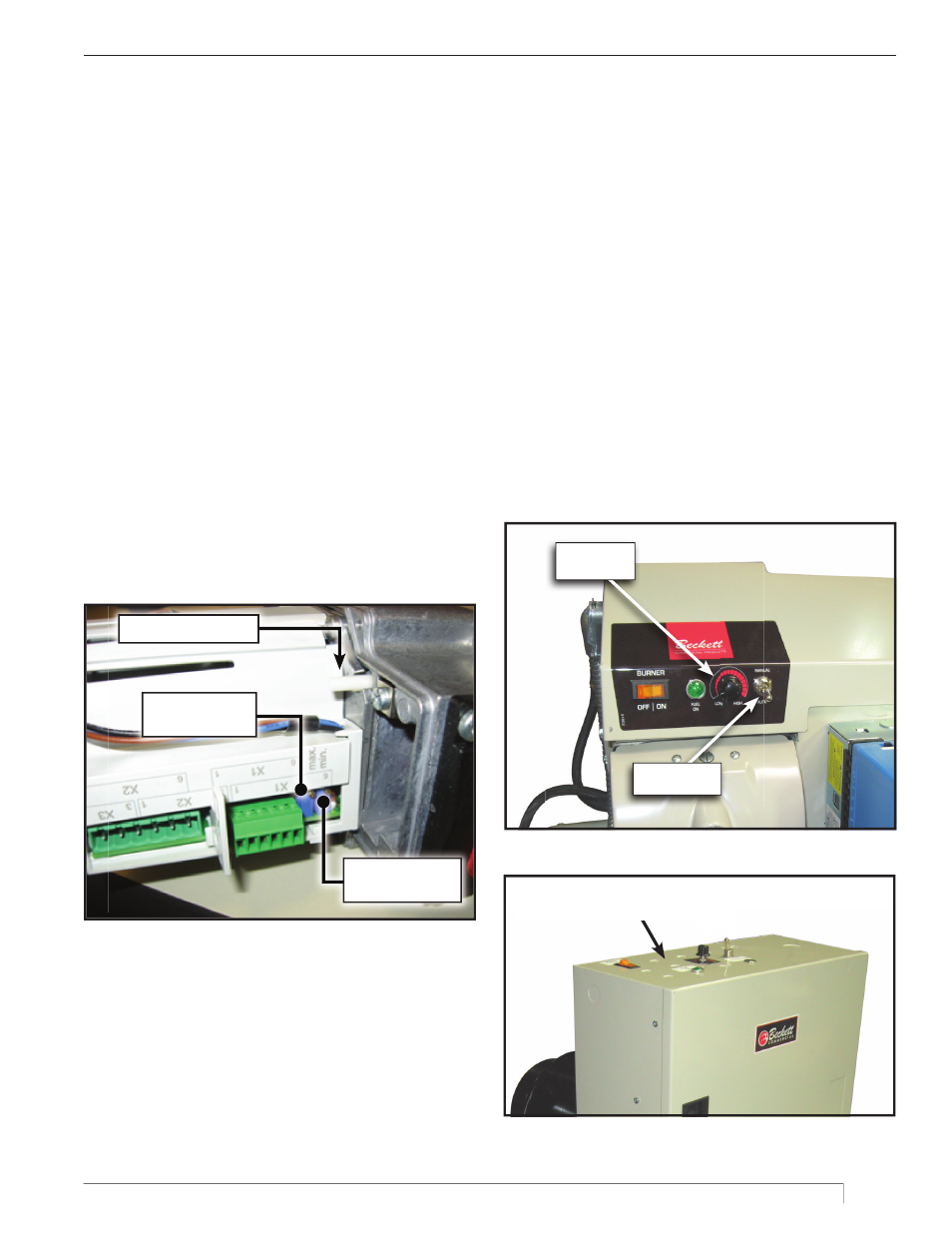
Maximum position
potentiometer
Cam disengaging pin
Minimum position
potentiometer
IV. Adjustment Instructions
Modulating burners are provided with manual controls that
allow set-up adjustment of the burner (
Figures 6 and 7
).
When the Manual / Auto switch is in the Manual position,
control of the damper position is set by the fi ring rate
potentiometer. When the Manual / Auto switch is in the
Auto position the fi ring rate potentiometer has no effect
on damper position, and the damper is controlled by the
fl ame safeguard during start-up and shut-down and by
the boiler’s modulating control during the run interval.
For 135 OHM controls only, If the Manual/Auto switch
is in the Manual position and the boiler pressure (or
temperature) approaches the control limit set on the
boiler’s modulation control (or lead / lag or building
automation system), that control will over-ride the
manual control and drive damper position back to low.
This feature can be used to limit the fi ring rate when
warming up a cold boiler.
Firing Rate
Potentiometer
Manual/Auto
Switch
Figure 6
Burners with a panel will have their manual
controls located on the top of the panel.
Figure 7
A notch in the white spacer at the base of the cam stack
indicates the position of the damper by its alignment with
the degree marker on the damper position label (Shown
in
Figure 4
). To set a cam, turn that cam’s adjustment
screw until the pointer on the cam aligns with the desired
setting on the white spacer between cams.
The burner’s damper can be manually rotated by
disengaging the motor’s gear train from the cam stack
(Shown in
Figure 5
).
1. Press in and towards the center of the motor on the
cam disengaging pin. It will allow the damper to
move while the cam remains stationary.
2. After adjusting the cams for high and low fi re
settings it is important to set the damper position
between the adjusted limits. If the damper position
is left outside the adjusted limits the actuator may
not be engaged until the end of the fi rst operating
cycle.
3. WARNING! Re-engage the pin by pushing it
toward the side of the motor and allowing it to
pop out to its original position, otherwise the
motor will rotate without moving the damper.
If the proportional controller signal does not fully
open or close the damper to its high or low fi re setting
during modulation, or if modulation is not linear across
the control range, it may be necessary to adjust the
maximum or minimum position potentiometer in the
damper motor (Shown in
Figure 5
). See the SQM40
manual in the burner’s literature package for detailed
instructions. Note: Both potentiometers require 30
turns to span their range. Don’t give up too soon.