Iii. damper motor components, Ii. wiring – Beckett SQM40 User Manual
Page 2
2
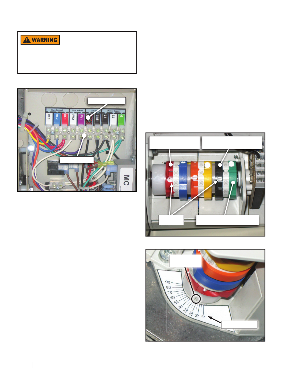
III. Damper Motor Components
The damper motor positions for high fi re and for low fi re
are set by adjustment of individual cams in a cam stack
(Shown in
Figure 3
). Only three of the cams in this
motor are active, the red, black and green cams.
○
The red cam limits the maximum position of the
motor to the burner’s high fi re setting.
○
The black cam limits the minimum position of the
motor to the burner’s low fi re setting.
○
The green cam could be used to set a third position,
for example an off position for the damper. We do
not use the green cam, but we recommend that it be
set to the same position as the black cam.
Indicating Notch for
Damper Position
Damper Position Scale
Figure 4
Red High Fire Cam
(Example:Red Pointer set at 90)
Black Low Fire Modulation Limit Cam
(Example: Black Pointer set at 25)
Green Low Fire Limit Cam
(Example: Green Pointer set at 25)
Figure 3
II. Wiring
Color Coded Label
Terminal Strip
Figure 2
Electric Shock Hazard
Turn off all electric power to the burner before
servicing.
y
If power is required for adjustments, use extreme
care while working near live conductors.
For standard construction burners the junction
box contains a color coded terminal strip showing
connections for control system power (and blower
motor power for 120 VAC blower motors), limit string
connections, gas valve connections, and rate control
connections. The terminal strip markings match the
wiring diagram specifi c to your burner. All of your
control connections are to be made to this terminal
strip. For burners with blower motors operating at a
voltage greater than 120 VAC the junction box will have
a separate motor contactor section with its own power
connections. Refer to the wiring diagram supplied with
your burner for connection details.
Adjusting
Screws