Iii. cam installation, Option c - flush mount with bracket, thick panel, Use option b for the following models only – Kidde 001798 Mounting Instructions User Manual
Page 2
2
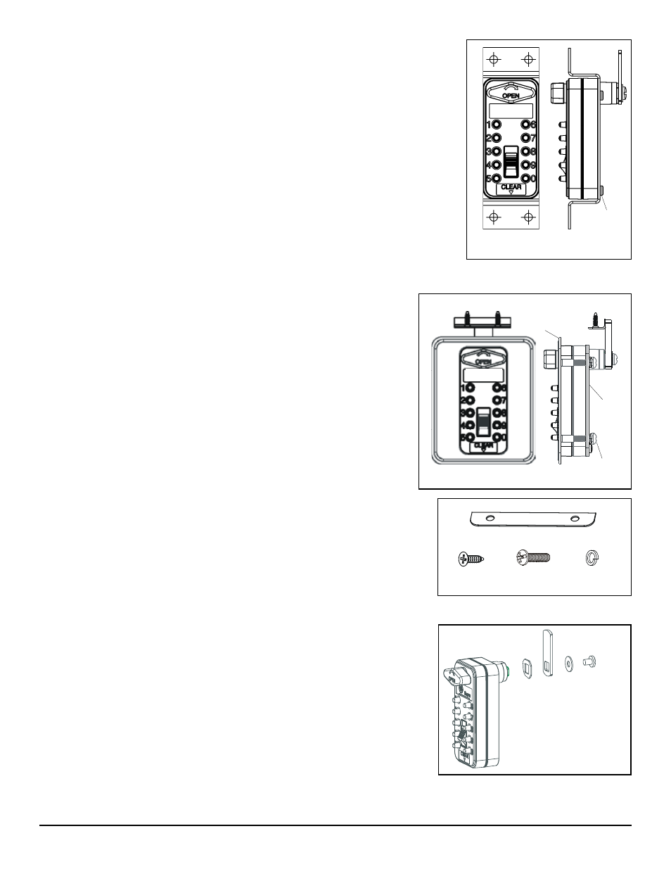
Body Screw
(4)
Option B - Flush Mount with Bracket, Sheet Metal Cabinet
Use Option B for the following models ONLY:
001764, 001765, 001766, 001767, 001768, 001773, 001786, 001787, 001788, 001789,
001790, 001798
Mounting the Lock using the flush mount option requires the use of a mounting bracket.
1. Use Template B to determine the dimensions and hole locations.
2. Position the Lock and mounting bracket in place and install the four #6-32 torx Body Screws
through the bracket into the Lock body and tighten. Do not exceed 15 in-lb. of torque.
Note: The screws are designed to cut threads into the Lock body as they are installed.
3. Attach the mounting bracket to the panel with your choice of fasteners through the four holes
at the outer corners of the bracket.
4. Proceed to Cam Installation (Section III).
Option C - Flush Mount with Bracket, Thick Panel
Use Option C for the following models ONLY:
001827, 001828, 001829, 001830, 001831, 001832, 001833, 001834
This mounting option is intended for panels of 3/4" (± 1/16") thickness and requires
the use of a thick panel bracket.
1. Use Template C to determine the dimensions and hole locations; make sure the
cam outline extends 1/4” beyond the door edge.
2. Cut the hole for the Lock and four corner holes using the template as a guide.
3. Mount the backplate to the Lock using the four body screws; torque should not
exceed 15 in-lbs.
4. Position the faceplate flush to the front of the cabinet, aligning the plate with the
four corner holes.
5. Insert the Lock with backplate into the large hole through the back side of the
cabinet. Check for any gaps between the backplate and cabinet. If a gap is present,
use the shims provided to fill the space between the backplate and cabinet.
6. Attach the backplate to the faceplate by installing the four Phillips screws and lock
washers into the four corner holes in the backplate and tightening.
7. To mount the strikeplate, measure 1.35" in from the cabinet face and cut a rectan-
gular hole. Drill two 1/16" pilot holes and mount with the two flat phillips screws.
8. Proceed to Cam Installation (Section III).
III. Cam Installation
The Lock includes a camshaft which extends from the back of the Lock body and ends
in a 5/16" square protrusion, designed to mount and orient the cam arm. An optional
90° or 180° stop washer must be used between the cam arm and Lock body to limit
the rotation of the cam.
The stop washer, cam arm, and round washer are secured to the Lock using the 10-24
Cam Screw.
Shim - Optional (2)
Flat Phillips (2)
3/4” Phillips
(2-4)
Lock Washer
(2-4)
Round
Washer
Lock Body
Lock with Bracket
Strikeplate
Faceplate
Lock with Thick Panel Bracket
Backplate
Body
Screw
Stop Washer
Cam
Screw
Cam Arm