Vernier Centripetal Force Apparatus User Manual
Page 3
5
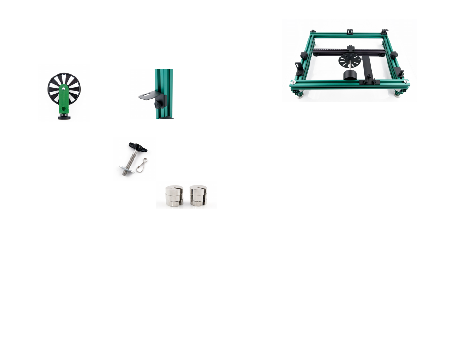
Ultra Pulley and Pulley Bracket
The Ultra Pulley and Pulley Bracket allow a torque to be applied to the Rotational
Shaft. Secure the Ultra Pulley to the bracket using the included 1/4 x 20 screw.
Attach one end of a string to the 3-Step Pulley mounted on the Rotational Shaft.
Attach a small mass to the other end of the string. Run the string over the Ultra
Pulley and allow it to fall to apply a torque to the Rotational Shaft.
Ultra Pulley
Ultra Pulley Bracket
WDSS Screw and Clip
The WDSS Screw allows you to
attach the WDSS to
the rotating beam. The Clip connects
the WDSS to the hook
on the Sliding Carriage.
Masses
Four 50 g masses and four 100 g masses are included in
the apparatus. They slip into the carriages to allow you
to vary the masses of the carriages.
Assembly and Storage of the Frame and Support Legs
The apparatus is shipped flat, and it can be stored flat when not in use. The Rotating
Assembly and Rectangular Frame come completely assembled. The brackets for the
Dual-Range Force Sensor, Vernier Photogate, and Vernier Ultra Pulley are also
preinstalled. The Support Legs are stored on the sides of the frame. Remove the
knob of the knob screw that holds each leg and use the knob screw to attach each
Support Leg to the bottom of the frame, then replace the knob and tighten. Reverse
this procedure to store the equipment.
6
Rectangular Frame stored flat. Support legs attached to
the underside of the side vertical frame members.
Leveling the Apparatus
Follow these steps to level the apparatus.
1. Secure the Counterbalance Carriage to the outer end of the Rotating Beam.
2. Place three of the Masses in the carriage.
3. Use a flathead screw driver to lower each foot on the CFA footer to its lowest
height.
4. Give the Rotating Beam a very slow spin and watch its motion. The beam will
tend to settle to its lowest point. Confirm the location of lowest point by spinning
the beam a couple more times.
5. Raise the lowest end or side of the apparatus by increasing the height of the
nearby footer or footers.
6. Repeat Steps 4 and 5 until the beam spins without returning to a consistently low
spot.
Attaching the Carriages to the Rotating Beam
It is important to attach the carriages in the proper orientation on the Rotating Beam.
The beam is not symmetric about the Pulley Guide located near the middle of the
beam. With the ruled side of the rotating beam facing you, the Sliding Carriage goes
on the right and the Counterbalance Carriage goes on the left.