Recommended settings – EVH 5150III 100 Watt Amp Head User Manual
Page 8
8
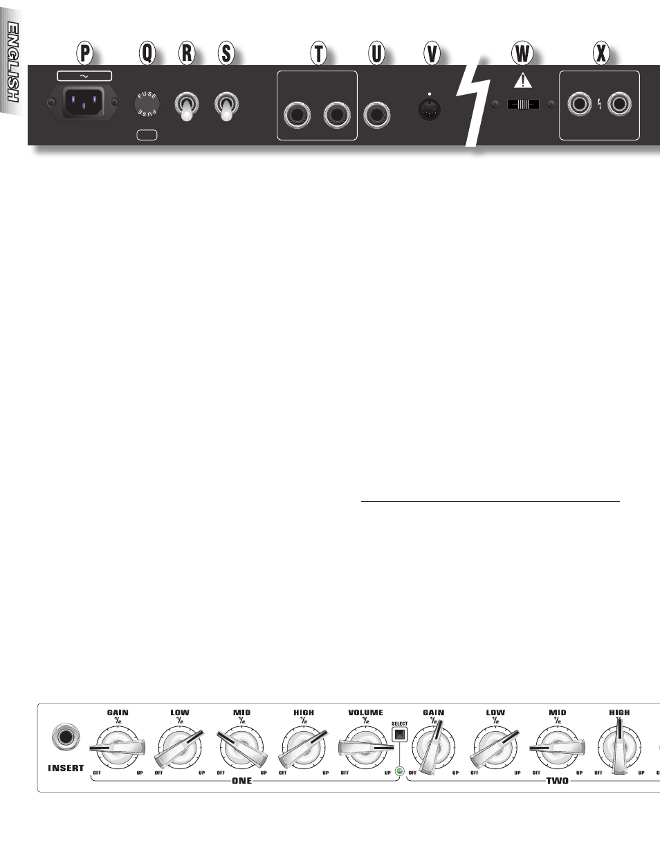
P . POWER INPUT—Connect the included power cord in
accordance with the voltage and frequency ratings listed
on the rear panel of the amplifier.
Q . FUSE—Replace with same rating only.
R . POWER—Turns the amp ON-OFF. After turning the
POWER switch to ON, wait 30 seconds for the tubes to
warm up, then turn the STANDBY switch to ON to take
the amp out of STANDBY mode. Before turning the amp
POWER to OFF, place the amp in STANDBY by tuning this
switch to OFF for 10 seconds before turning the POWER
to OFF.
S . STANDBY—Place this switch in the OFF position to put
the amp in STANDBY mode. This should be done when
taking a break from playing or before turning the amp
POWER to OFF as outlined above in the POWER section.
Using the STANDBY mode prolongs the life of the tubes
in the amp.
T . EFFECTS LOOP—Useful for obtaining maximum per-
formance from rack-mount or pedal effects like Reverb,
Delay, Chorus, etc. Connect SEND to the input of your
effects unit and RETURN to the effect's output.
U . PREAMP OUT—Connect to another amp’s EFFECTS
RETURN or POWER AMP IN for simultaneous multiple
amp use. This output may also be used to send the pre-
amp’s signal directly to a mixer.
V . FOOTSWITCH—Connect the cable of the supplied
footswitch here (See EVH FOOTSWITCH {Y} next page).
W . LOAD IMPEDANCE—Selects the output impedance of
the amp (4, 8 or 16 Ohms) to match the speaker load.
NOTE: The 5150-III 412 speaker enclosure (recommended)
has an impedance of 16 Ohms. When using one 5150-III 412
speaker enclosure, set the LOAD IMPEDANCE switch to “16Ω.”
When using two 5150-III 412 speaker enclosures, set the LOAD
IMPEDANCE switch to “8Ω.”
X . SPEAKER OUTPUTS—For connection to speaker
cabinet(s). When using one speaker cabinet, either jack
can be used. Use only a high-quality unshielded speaker
cable.
NOTE: A speaker must always be plugged into one of the
speaker jacks when the EVH amplifier is ON or damage may
occur. Switch the amplifier "OFF" or to "STANDBY" while
changing speaker connections or impedance settings.
Speaker Configurations are as follows:
SPEAKER
SPEAKER IMPEDANCE
JACK
JACK
SETTING
16Ω + NONE = 16Ω
16Ω + 16Ω = 8Ω
8Ω + NONE = 8Ω
8Ω + 8Ω = 4Ω
4Ω + NONE = 4Ω
Recommended Settings
POWER
ON
OFF
T4A L
250V
FUSE
LOAD
IMPEDANCE
4½ 8½ 16½
ON
SEND
RETURN
EFFECTS LOOP
FOOT
SWITCH
PREAMP
OUT
STANDBY
OFF
INPUT
POWER
V Hz 533W
4½ min TOTAL
100W
PARALLEL
SPEAKER OUTPUTS