Cabletron Systems BRIM-T6 User Manual
Page 21
INSTALLATION
2-7
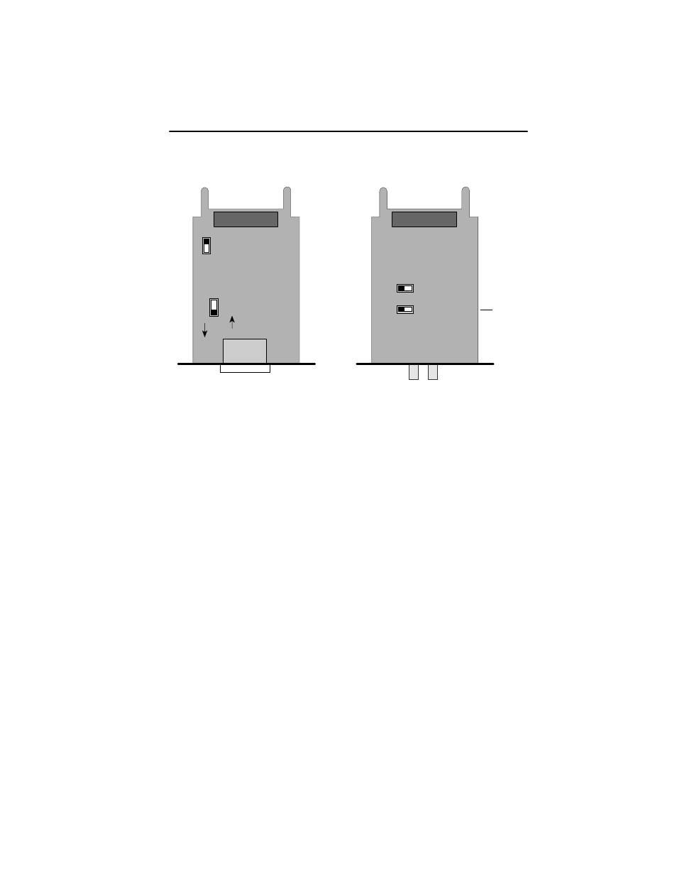
Figure 2-4. TPIM Configuration for Station Applications
NOTE: If the switch locations on a TPIM do not match the example
locations illustrated in Figure 2-4, refer to the TPIM Reference Card
included with the TPIM. The TPIM Reference Card outlines switch
locations and settings. For additional help, call Cabletron Systems
Technical Support Department (see Section 1.5).
Top View
(See Below For Settings)
TPIM-T1/TPIM-T2/TPIM-T4
Phantom Switch Settings
1 = Cabletron Device (Default)
0 = Non-Cabletron Device
RI/RO-STN Switch Settings
RI/RO = Ring In/Ring Out (Default)
S = Station (BRIM-T6 Functional)
P
H
A
N
T
O
M
S RI/RO
1
0
TPIM-F2/TPIM-F3
Fiber Key Settings
Ctron = Cabletron Device
802.5 = BRIM-T6 Functional
RI/RO-STN Switch Settings
RI/RO = Ring In Ring Out (Default)
STN = Station (BRIM-T6 Functional)
S
T
N
RI/RO
8
0
2
.
5
Ctron
PN . . . . .-0X REV
Part
Number
- 2E42-27R (164 pages)
- 6H122-16 (158 pages)
- 24 (35 pages)
- 9T427-16 (16 pages)
- bridges (132 pages)
- CSX200 (88 pages)
- 2208 (158 pages)
- SM-CSI1076 (69 pages)
- SEHI-22 (93 pages)
- 9T425-16 (40 pages)
- 6000 (180 pages)
- 1800 (448 pages)
- ESX-1380 (86 pages)
- DLE23-MA (202 pages)
- 2E43-51 (168 pages)
- 5000 (83 pages)
- 6H253-13 (62 pages)
- Lancast Media Converter 7000 (108 pages)
- SmartCell 6A000 (102 pages)
- 9G421-02 (12 pages)
- SEH-22 (56 pages)
- 9A000 (180 pages)
- SEH-24 (64 pages)
- 6E123-26 (184 pages)
- STS16-20R (258 pages)
- 2E43-27 (164 pages)
- Cabletron MicroLAN 9E132-15 (36 pages)
- 9F120-08 (28 pages)
- 9E428-36 (18 pages)
- Device Management Module Dec GigaSwitch (65 pages)
- ELS10-26TX (18 pages)
- MICROMMAC-22T (105 pages)
- CSX1200 (644 pages)
- 7H02-06 (36 pages)
- 150 (106 pages)
- 9F206-02 (10 pages)
- MMAC-Plus 9T122-24 (27 pages)
- SEH100TX-22 (52 pages)
- 7C03 MMAC (16 pages)
- 2H253-25R (64 pages)
- TRXI-42 (92 pages)
- 7C04 (150 pages)
- 2H22 (120 pages)
- 2000 (196 pages)
- 7C04 Workgroup (25 pages)