PDR Mounts fcp50 User Manual
Page 7
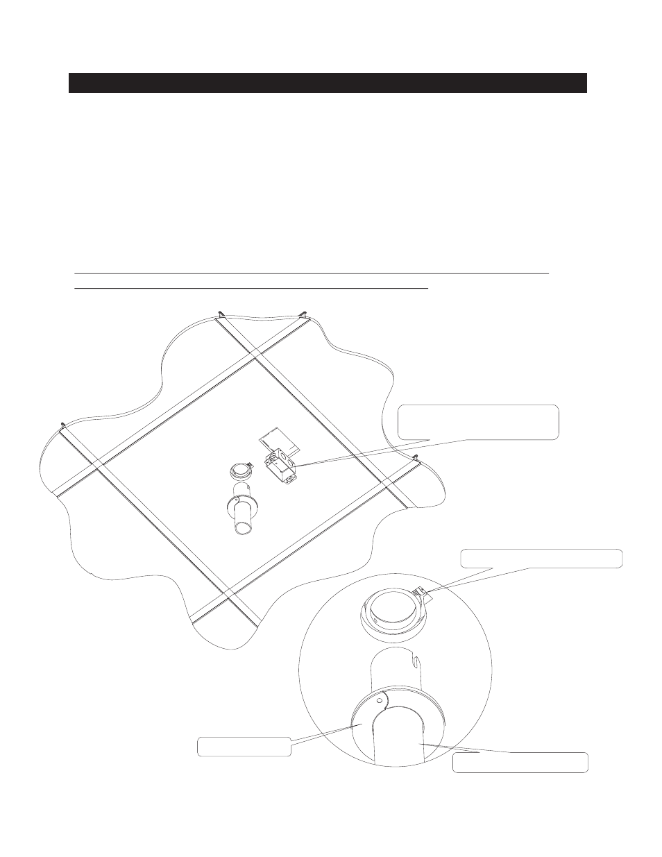
ELECTRICAL BOX AND LOCKING SCREW INSTRUCTIONS
1.
This operation should only be carried out by a qualified electrician, following local codes and
regulations.
2.
Cut the electrical outlets thru the ceiling tiles ( optional ). Allow for the screw holes for the box on the bottom
side.
See fig 8
3. Attach the electrical box (not supplied) .
See fig 8
4.
5. Install the 1 ½”pipe ( not supplied ) into the (#1) FCP mount.
See fig 9
6. Lift the FCP with the 1 ½” pipe attached to tighten the
M6 x 16mm screw . Lower the unit back over the
ceiling grid bars and tighten the four
screws
See fig 3
7. Install the chrome trim ring (#10) onto the 1 ½” pipe . Clip the ends together and slide up to the ceiling tile.
See fig 9
9.
NOTE be sure to adjust the (#11) wire rope and (#6) Quick locks after the projector is mounted
onto the 1 ½” pipe drop. Failure to do so may cause the mount to fall.
Be sure to disconnect the power source before connections are made.
Run wiring and make connections per local codes and regulations .
#3
(# 3)
7
TRIM RING #10
CUT-OUT FOR SET SCREW # 3
1 ½” PIPE NOT SUPPLIED
STANDARD FLUSH MOUNT
ELECTRICAL BOX
fig 8
fig 9