Fig 4 fig 5, Fig 6, Fig 7 – PDR Mounts pdm110f User Manual
Page 4
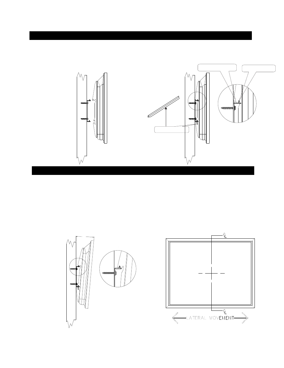
3. MOUNT THE DISPLAY TO THE WALL MOUNT BRACKET
Fig 4
Fig 5
4. Adjust lateral movement
Lateral Movement:
Fig 6
4
Fig 7
Once the installation of the display on the wall is complete you can still move the display left to right to optimize the final viewing position, by gently sliding the unit on the wall
bracket. The adjustment distance will vary depending on the display model being installed.
5°
Slot 1 position for 5 deg tilt
Slot 2 position for no tilt
Locking bar
Lift the display with the brackets attached, onto the wall plate.
See Fig4 Position the top in either slot 1 for 5 deg tilt or slot 2 for flat mounting See fig 5 and Fig 6
Insert the locking bar (C) as shown in fig 5 with the locking holes facing up to match the holes in the wall mount bracket (B) .
Make sure the display brackets
engage the rails on the wall mount bracket (B)
See fig 5. Secure with a padlock (not supplied) if required thru holes in the locking bar (C) and wall mount bracket (B)Fig 5