Fig 2, Fig 3, Panel display bottom edge – PDR Mounts pdm110f User Manual
Page 3
24
"
16 "
16
"
32
"
4.00
EQUAL
SPACING
WOOD STUDS
16
"
24
"
4.00
EQUAL
SPACING
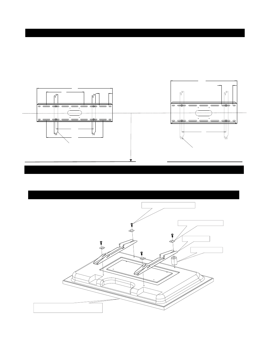
1. FASTEN MOUNTING PLATE TO WALL
Fig 2
2. SECURE THE DISPLAY BRACKETS TO THE MO NITOR
NOTE: Do not over tighten the bracket mounting screws as damage to the display internal mounting threads could occur.
The bracket must be secured to the wall studs capable of holding at least (4) times the weight of the unit. The wall bracket should be mounted at the same horizontal center line
as the display center line ( viewing horizontal center line). Using the four lag bolts( E ) and washers supplied ( D ) Level and secure the mounting plate to the center of
the wall studs Pre drill 3/16” (5mm) hole for lag bolts
fig.2
Model # 110
Model # 120
FLOOR LINE
VIEWING
HORIZONTAL
CENTER LINE
(std construction 2 x 4 studs/1/2” wallboard)
Fig 3
3
Mounting hardware F,G,H,K,L , M, O,P
Square Multi-mount washer ( I )
Panel display bottom edge
WOOD STUDS
(std construction 2 x 4 studs/1/2” wallboard)
Display bracket ( A )
PLASTIC SPACER (J )
Lay the display panel face down on a protected surface. Position the left and the right hand bracket ( A ) with the slots facing towards the top.See
Fig.3. Note bottomedge!
Using the proper screws,( F,G,H,K,L or M ). plastic spacer ( J ) .(may not be needed if display has a flat mounting surface) and square multi-mount washers (I )
supplied Position the brackets equal distance from top to bottom and tighten hardware.