PDR Mounts swm050 User Manual
Page 4
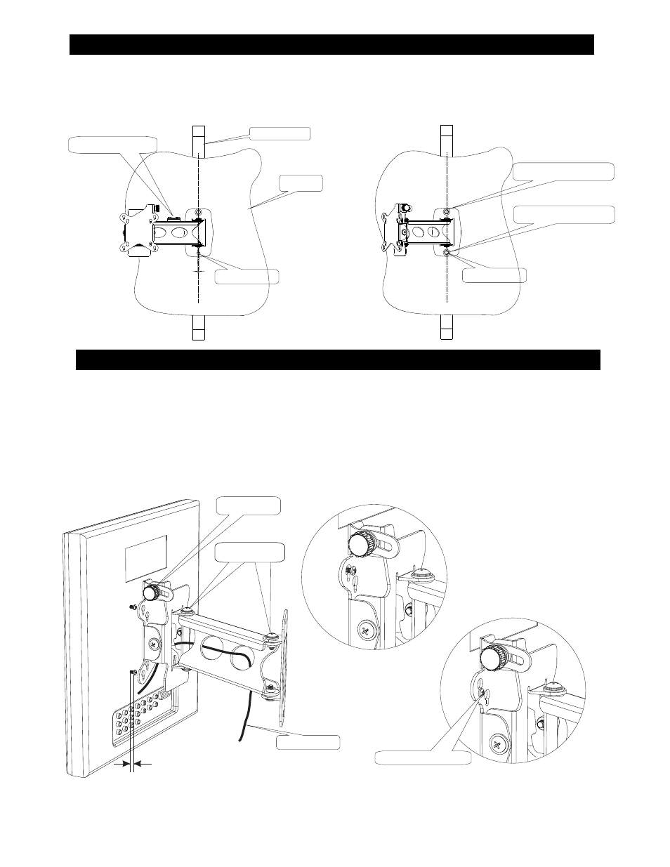
WALL MOUNTING INSTRUCTIONS
DISPLAY MOUNTING INSTRUCTIONS
4
Place the display face down on a soft protected surface. Using the four screws supplied #15, screw into the back of the display
leaving the head about 1/8” from bottoming.
See fig 3
Place the display onto the mount thru the keyhole slots in the SWM-050 ( # 4).
See fig 4
After the display is secure in the bottom of the keyhole slots tighten the screws.
See fig 5
Tighten the tension bolts and knob to suite your preference and the weight of the display. This will prevent the mount from creeping
from the desired location .
See fig 3
Route the wires thru the holes provided in the mount to suite.
See fig 3
(If your display back is not flat it may require the use of the spacer and screws supplied
#11 and #14) .
Determine a suitable mounting position, making sure there is enough room for the mount and display to swing from left to right.
The
SWM-050 must be mounted centered on a wall stud. See fig 1
Mark the location with a pencil, and using a 3/16 drill bit, drill a pilot hole for the mounting hardware #12 . Secure the top of the
bracket with lag screw #12 and washer #13 .
Swing the mount to the left or right against the wall, and using a level (not supplied) adjust and secure the bottom hardware #12 and
#13
See fig 2
1/8” approx
Fig 3
Fig 4
Fig 5
Adjustment slot
Level (not supplied)
Fig 1
Fig 2
Hardware #12 & #13
Hardware #12 & #13
Wall stud
Drywall
Tension bolts
Tension knob
Adjustment slot
Typical wiring
Secure in this position