Fig 4 fig 5 fig 6 – PDR Mounts awm125-vesa User Manual
Page 6
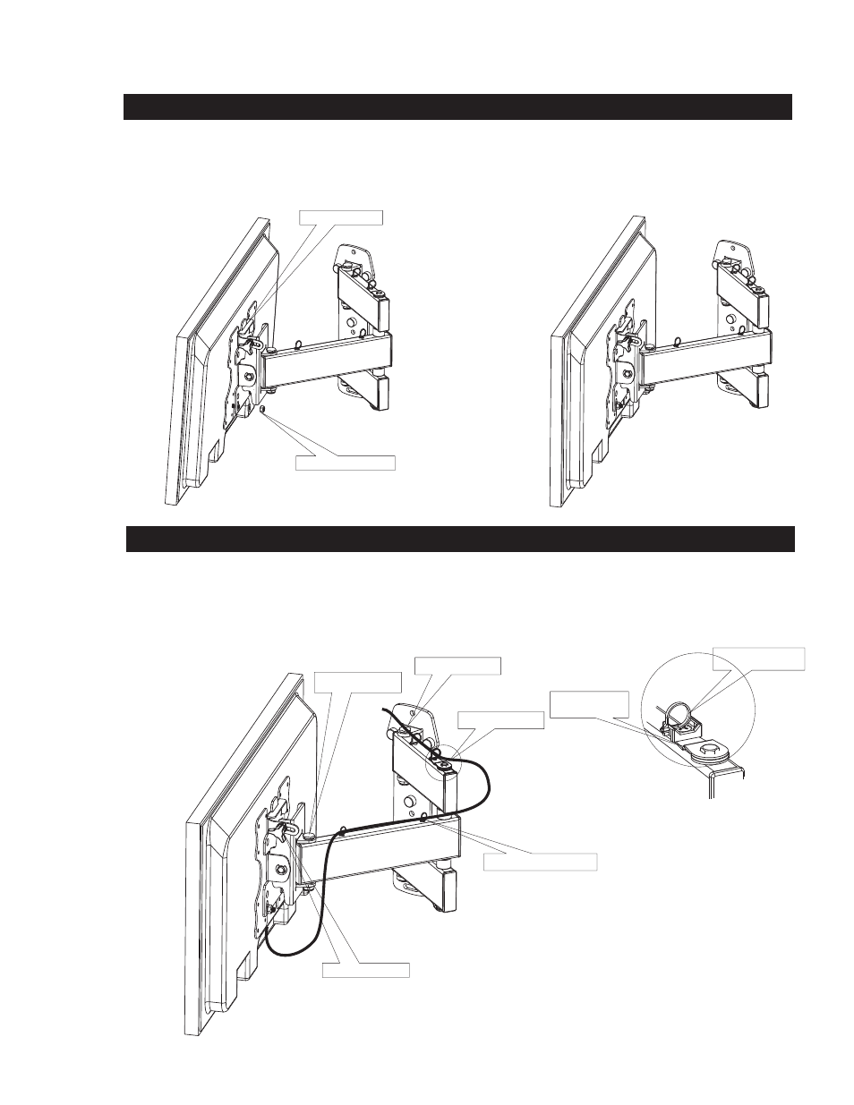
3. Mounting the display onto the AWM125 Articulating arm
3. Final adjustment and cable management
Screw lock tab
Plastic tie holder
6
Fig 4
Fig 5
Fig 6
1: With the VESA adapter plate attached to the display, lift and place the slot on top of the
adapter plate onto the tab of the AWM125 tilt
plate
See fig 4
Allow the display to swing down and locate flush with the studs engaging into the slots on the AWM125 mount.
See fig 4
2:Using the washers and nuts supplied, fasten the display to the
AWM125 articulating arm. See fig 4 and 5
VESA
1: Adjust by tightening the tension bolts to suit the desired movement
See fig 6
2: Lift the screw lock tab to access the tension bolts and adjust the tension on the arm center.
Remember to replace the screw lock tab otherwise the mount could fail.
3: Adjust the tilt by loosening the tension knob on the side of the AWM125 and adjust for best viewing angle.
See fig 6
4: For cable management, place the plastic tie holders and screw (item 8 & 7) in the desired holes, and use zip ties to attach the wires.
5: Make sure you articulate the mount from side to side looking for any pinching of the wires.
TENSION BOLT
TENSION BOLT
TENSION BOLT
CABLE MANAGEMENT
TENSION KNOB
WASHER AND NUT
Slot and Tab