Nexen RB45B 968192 User Manual
Page 6
FORM NO. L-21326-C-0513
6
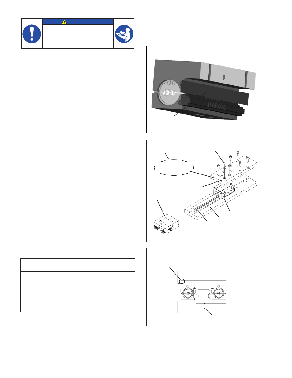
Figure 5
See Figure 6
Rail Brake
Rail*
Bearing*
*Customer Supplied
Table (end view)
Socket Head
Cap Screws
Base*
Table*
IMPORTANT
Carefully follow Steps 1-4 to ensure
a successful Rail Brake installation.
Do not use the dowel pin holes for
brake installation. These holes are for
manufacturing purposes only.
Figure 6
Table (end view)
Datum
Plane
Note: Brake width is slightly under carriage width.
Small gap (0.010) to be expected.
Shim
Figure 4
MOUNTING ON A RAIL
Assembly Shims: This installation recommends the
use of assembly shims to ensure proper alignment. The
assembly shim is a .08mm (.003”) rectangular shaped
piece of shim stock that runs the full length of the
facings. See Figure 4 for an example. Each shim will be
different depending on rail type. The shim is customer
provided and one is required for each side.
1. Disengage Brake.
a. SPRING ENGAGED VERSION: Apply
minimum 5.5 BAR (80 PSI) to air inlet of brake
to disengage. (Refer to AIR CONNECTIONS
for details).
b. AIR ENGAGED BRAKE: Disengaged is the
default position.
2. Using installation shims, slide brake onto rail with
shims between the facing and the rail on both sides.
The installation shims are approximately the same
thickness as the gap between the facing and the
rail. Because of this some drag is expected while
completing this step.
3. Once brake is approximately in position, install
mounting screws finger tight. Do not tighten at this
point.
4. Engage Brake, this will center it on the rail, then
tighten the mounting screws. Do not remove shims
at this point.
Table 1
Model
Socket Head
Cap Screw Size
RB15
M5 x 0.8
RB20
M6 x 1.0
RB25
M8 x 1.25
RB30
M10 x 1.5
RB35
M10 x 1.5
RB45
M12 x 1.75
- RB35B 968164 RB25B 968126 RB20B 968142 RB15B 968136 RB35B 968176 RB30B 968113 RB25B 968151 RB20B 968180 RB15B 968177 RB45B 968190 RB35B 968163 RB30B 968110 RB30B 968106 RB25B 968189 RB25B 968150 RB20B 968147 RB15B 968141 RB30B 968114 RB45B 968193 RB35B 968101 RB30B 968102 RB25B 968130 RB20B 968145 RB15B 968135 RB45B 968197 RB35B 968166 RB45B 968187 RB25B 968152 RB25B 968153 RB35B 968165 RB30B 968105 RB20B 968146 RB15B 968139 RB45B 968206 RB25B 968162 RB30B 968219 RB45B 968221 RB35B 968220 RB25B 968112 RB20B 968218 RB15B 968217 RB45B 968205 RB35B 968204 RB30B 968203 RB25B 968202 RB20B 968201 RB15B 968200 RB20B 968186 RB35B 968169 RB25B 968156 RB20B 968144 RB15B 968138 RB45B 968185 RB35B 968170 RB30B 968120 RB25B 968157 RB20B 968125 RB15B 968131 RB30B 968119 RB35B 968198 RB15B 968137 RB45B 968195 RB35B 968168 RB25B 968155 RB20B 968143 RB45B 968194 RB35B 968167 RB25B 968154 RB20B 968148 RB30B 968108 RB30B 968118 RB45B 968184 RB35B 968171 RB25B 968158 RB20B 968127 RB15B 968132 RB45B 968183 RB35B 968172 RB25B 968159 RB20B 968128 RB15B 968133 RB45B 968182 RB35B 968173 RB25B 968160 RB20B 968129 RB15B 968134 RB30B 968115 RB30B 968117 RB30B 968116 RB45B 968181 RB35B 968174 RB35B 968175 RB30B 968107 RB25B 968161 RB20B 968178 RB15B 968179