Assembly instructions 4/4, Step 5, Step 6 step 7 – Home Styles 5180-10 User Manual
Page 5
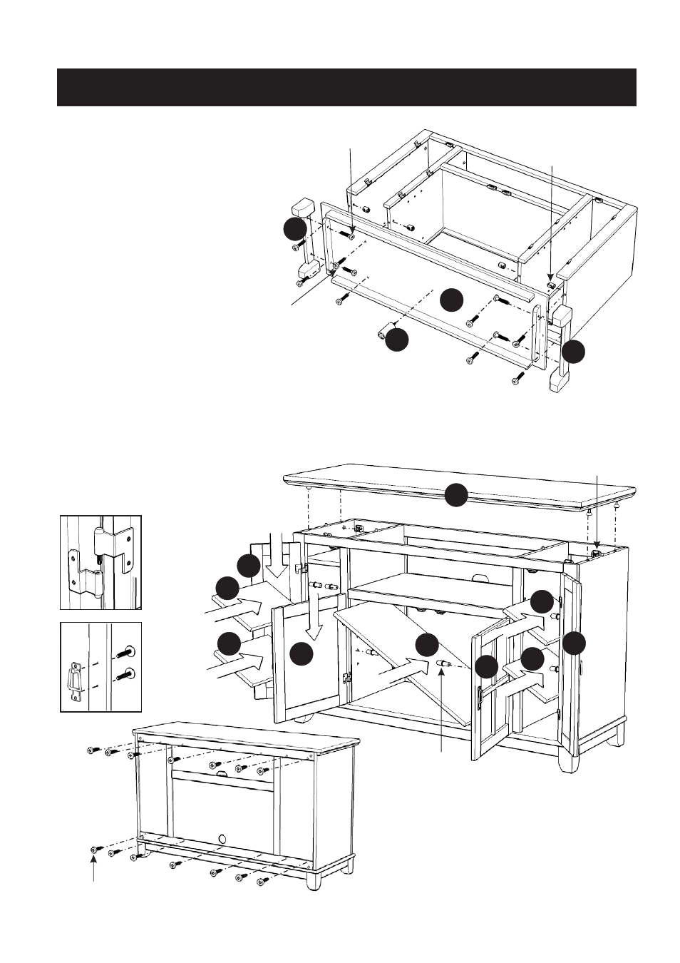
Assembly Instructions 4/4
Attach Base (P) to unit with
Head Cap Bolts and
Cross Dowels.
Attach Legs (Q1) to unit with
Head Cap Bolts.
Attach Leg (Q2) to unit.
STEP 5
Place Top (A) onto the unit, using Cam Locks.
Attach Doors (R), (S), (T) and (U) by sliding the door lift hinges
into the side panels lift hinges. (see Figure 1)
Assemble Pull Handles to Doors (R), (S), (T) and (U) with Machine Screws. (see Figure 2)
Insert Adjustable Pins into side panels and middle panels at the desired level.
Place Shelves (O) and (N)
into position.
STEP 6
STEP 7
Insert 14X Wood Screws from
the back of the unit, tighten up all
the Wood Screws.
(Figure 1)
(Figure 2)
A
R
S
T
U
O
O
O
O
N
Adjustable Pin
Wood Screw
Cam Lock
Q1
Head Cap Bolt (long)
P
Head Cap Bolt
Cross Dowel
Note: Please make sure unit is level
before tightening these screws.
Q1
Q2