Assembly instructions 3/5, Step 3, Step 2 – Home Styles 5530-09 User Manual
Page 3
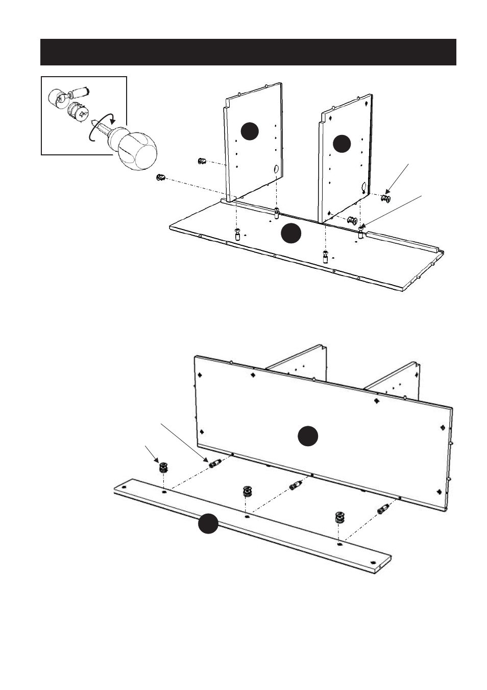
D1
D2
STEP 3
Assembly Instructions 3/5
Cam Lock
Screw
Cam Lock
Figure 1
Put the Cam Lock Screws into
the pre-drilled holes at the underside of Base (E).
Attach Back Support (F) to the unit with Cam Locks.
Cam Lock Screw
Cam Lock
F
E
E
STEP 2
Attach Middle Panel (D1)
and (D2) onto Base (E)
with Cam Locks. (see Figure 1)