Assembly instructions 2/4, Step1 – Home Styles 5536-09 User Manual
Page 2
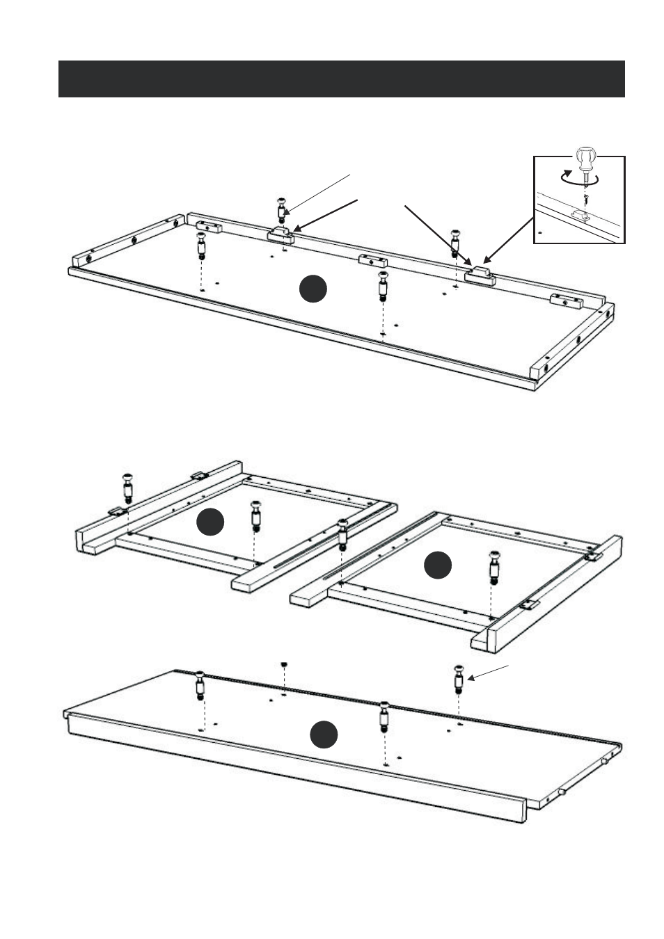
Cam Lock Screw
Magnet
B
C
E
A
Cam Lock Screw
STEP1
Assembly Instructions 2/4
Insert Cam Lock Screws into
the pre-drilled holes of Top (A), Side Panel (B), (C) and Base (E).
IMPORTANT
Do not tighten up all the screws until each part is properly assembled.
Please keep Hex Wrench in a safe place as you may need to tighten up the Head Cap Bolts in the future.
Figure 1
Attach 2X Magnets to
Top (A) by using Wood Screws
in the pre-drilled holes (see Figure 1).