Assembly instructions 2 – Home Styles 5516-06 User Manual
Page 2
Assembly Instructions 2
IMPORTANT
* Please keep Hex Wrench in a safe place as you may need to tighten up the Head Cap Bolts in the future.
* Do not tighten up all the screws until each part is properly assembled.
* Use a soft cloth between these parts and the fl oor.
* After assembly, item must be level to work properly.
Use the included adjustable levelers to level.
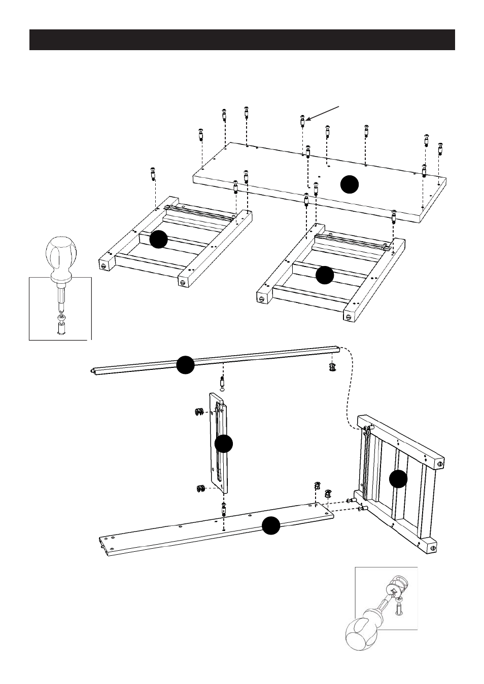
STEP 1
Insert Cam Lock Screws
into the pre-drilled holes
of Top (A) and
Side Frames (B) and (C).
(see Figure 1)
B
E
B
F
B
C
B
B
B
A
C
B
D
STEP 2
Attach Front Rail (D) and Back Stretcher (F) to Divider (E)
with Cam Locks. (see Figure 2)
Attach Side Frame (C) to unit with Cam Locks.
Cam Lock Screw
/4
Figure 1
Figure 2
This manual is related to the following products: