Vi - troubleshooting – Bradford White IGI-180R-10N User Manual
Page 37
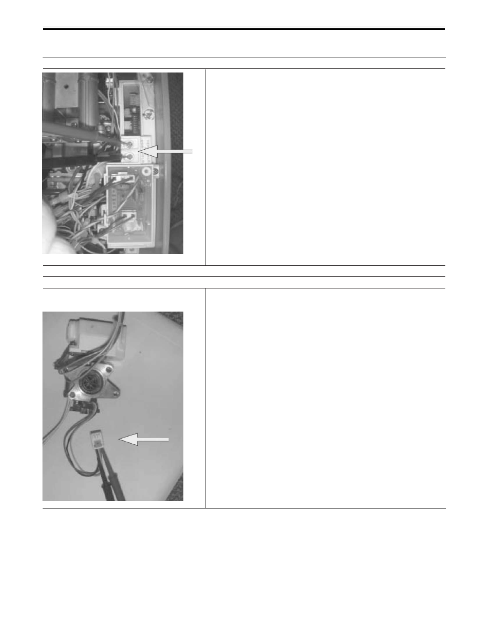
3) Is the remote control normal ?
No combustion (despite remote control indication)
1) Is the water flow sensor normal ?
37
Check voltage between the two remote control cable
connectors.
a.
Check the voltage between terminals on the
remote control terminal mount D
1
.
Normal: 11 ~ 13 VDC
If normal, check for an open circuit or short before
replacing the remote control.
Faulty: Replace PCB.
(Service Procedure IGI-2, page 49)
Check the water flow sensor.
a.
Check the voltage at PCB connector B4 , red and
black wires.
Normal: 11 ~ 13 VDC or 5.8 ~ 6.4K Ω
If normal, check (b) below.
Faulty: Replace the PCB.
(Service Procedure IGI-2, page 49)
b.
Check the voltage at PCB connector B4, yellow and
black wires.
Normal: 4 ~ 7 VDC or 1M ~ 1.2M Ω.
If normal, proceed to check item 2 on next page.
Faulty: Replace the water flow sensor.
(Service Procedure IGI-2, page 49)
VI - TROUBLESHOOTING
(cont.)
- EFR-1-60T1206EN (76 pages)
- S-2-TW65T6FBN (11 pages)
- D-38T-155-3X (1 page)
- PDX1-40S6FSX (13 pages)
- EF-100T-300-3X (92 pages)
- M-4-30T6FBN (28 pages)
- M-4-30T6FBN (32 pages)
- M-4-30T6FBN (28 pages)
- M-4-30T6FBN (40 pages)
- M-2-XR75S6BN (1 page)
- M-I-30T6FBN (30 pages)
- PDX2-75T6FBN (44 pages)
- U-1-75S6RN (1 page)
- U4-40T6FRN (12 pages)
- U1-50L6FRN (12 pages)
- U1-50L6FRN (28 pages)
- M-2-TW-50T6FSX (36 pages)
- M-4-XRTW50T6FSX (40 pages)
- TW4-50S-67FB-3X (40 pages)
- TW4-50S-67FB-3N (44 pages)
- M-2-TW-50T6FSX (44 pages)
- M-2-TW-50T6FSX (36 pages)
- C-SW2-TW75T10BN (8 pages)
- GX-2-25S6SX (28 pages)
- C-SW2-75T10BN (28 pages)
- S-2-65T6FBN (28 pages)
- PE-4-40T6FBN (68 pages)
- PE-4-403S6FBN (32 pages)
- PE-4-403S6FBN (16 pages)
- GX-2-25S6SX (28 pages)
- M-I-100T6SX (28 pages)
- C-SW2-75T10BN (4 pages)
- C-SW2-75T10BN (25 pages)
- HE-4-40S6FBN (16 pages)
- HE-4-40S6FBN (40 pages)
- UDS1-50S6FRN (32 pages)
- DH-50T-50FB-3X (40 pages)
- DS1-40S6FBN (32 pages)
- U-1-75S6RN (28 pages)
- U-75T-80R-3N (8 pages)
- D-4-403S6FBN (36 pages)
- D-4-403S6FBN (40 pages)
- GX-2-TW-25S6SX (40 pages)
- U-1-TW-40S6FRN (48 pages)
- M-1-TW-40S6FBN (40 pages)