Bradford White M-2-WH30L6SS User Manual
Page 15
15
WALL MOUNTING BRACKET INSTRUCTIONS
GENERAL
The wall mounted water heater should be installed as near as possible to the
service points, to reduce heat loss through the piping system. Wall
attachment hooks or bolts must be capable of supporting at least (3) times
the weight of the water heater full of water. If bolts are used, 3/8” (9mm) are
recommended. A template for bolt spacing is provided.
Using template provided in this manual, mark wall with bolt hole centerline
and attach the supporting bolts into the wall (and into the reinforcement
brace if applicable see Figure 4).
Carefully position and lower the water heater (Figure 3) so that the
supporting bolts slide into the bracket slots.
Tighten the supporting bolts until the bracket is tightly seated against the
wall.
NOTE: When properly installed, the water heater inlet and outlet pipes
should be at the bottom of the water heater with the electrical connections in
the rear of the water heater.
NOTE: Depending on wall construction, a reinforcement brace MUST be
permanently attached to the supporting structure (studs) at the wall mounting
bracket location and at the bumper location (Figure 4) prior to mounting the
water heater to the wall.
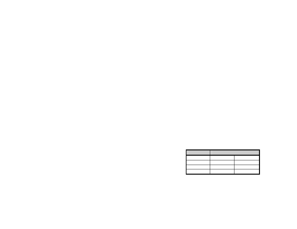
The vertical distance between the wall mounting bracket and the bumper is
as follows:
MODEL
“A”
MIWH6U
11 1/2 in
292.1 mm
MIWH12U
11 7/8 in
301.6 mm
MIWH20L
17 3/4 in
450.8 mm
MIWH30L
22 1/2 in
571.5 mm