Thermal well testing, Gas control testing – Bradford White TW4-75S-76B-3X User Manual
Page 26
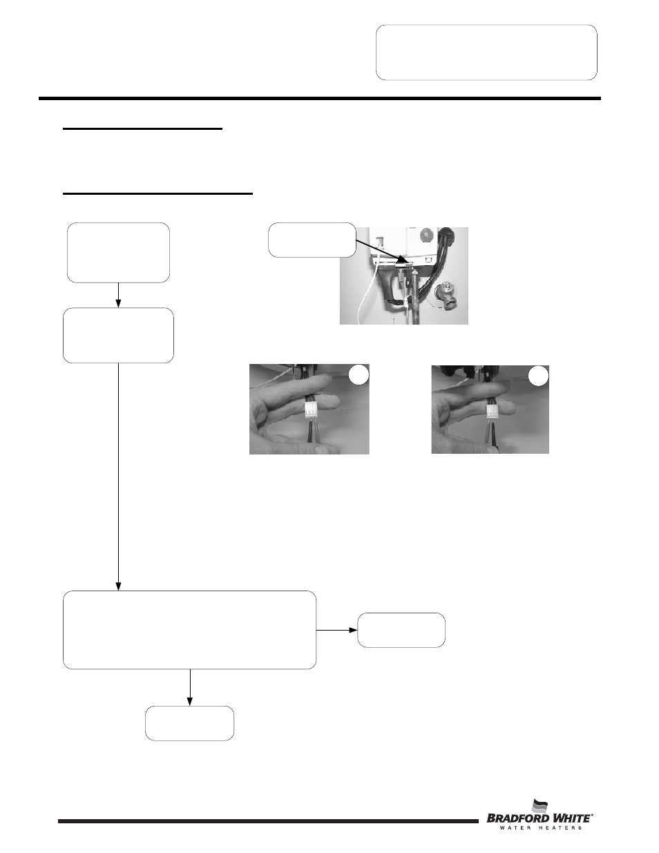
Thermal Well Testing
(For water heaters with serial numbers that begin
with “J” or sooner.)
Position gas valve power
switch to the “OFF” position
and disconnect thermal well
harness from gas control.
N
Y
Using a multi-meter set to the ohms setting, insert one meter probe into center wire
position of thermal well connector, insert the second probe into either of the outside
wire positions (see photo 19).
Alternate the probe on the outside position to the opposite outside wire position
(see photo 20).
Replace thermal well
(see page 26)
Using a multi-meter set to
the Ohms setting,
determine the resistance of
thermal well sensors 1 & 2
(see photos 19 & 20)
Disconnect thermal
well wire harness
19
20
Thermal well OK
TTW SERVICE PROCEDURE VI
Gas Control/Thermal Well Testing and
Replacement
Page 26
Gas Control Testing
See pages 29 & 30 for gas control
input & output testing.
Once the thermal well resistance values are known, the water
temperature must also be known to determine if the resistance
values are correct. See page 25 to obtain water temperature.
Are thermal well resistance values correct?
26