2 setup – Crown Audio 160MA User Manual
Page 10
Commercial Audio Series Mixer-Amplifi ers
Operation Manual
page 10
2 Setup
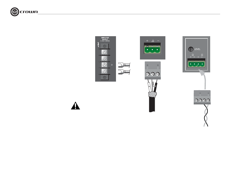
2.4 Choose Output Wire and Connectors
Amplifi er Output Connections: Slip the cable lugs under the output
screw terminals and tighten (Figure 2.6). Slide the supplied non-touch
cover over the output connections from top to bottom to cover them.
Crown recommends using pre-built or professionally wired, high-qual-
ity, two-conductor, heavy gauge speaker wire and connectors. You may
use crimp-on spade lugs for your output connectors. To prevent the pos-
sibility of short-circuits, wrap or otherwise insulate exposed loudspeaker
cable connectors. Cover the output connections with the supplied clear
non-touch cover by sliding the cover on.
Using the guidelines below, select the appropriate size of wire based
on the distance from amplifi er to speaker. The wire sizes apply to the
8-ohm tap.
Distance
Wire Size
up to 25 ft.
16 AWG
26-40 ft.
14 AWG
41-60 ft.
12 AWG
61-100 ft.
10 AWG
101-150 ft.
8 AWG
151-250 ft.
6 AWG
NOTE: Custom wiring should only be performed by qualifi ed
personnel. Class 2 wiring is required.
CAUTION: Never use shielded cable for output power wiring.
Use 2-conductor shielded cable and a 3-pin Phoenix-type connector for
Preamp Line Output (Figure 2.7).
Music-On-Hold Connections
If you have an external music source connected to the 135MA or
160MA, you can play its music over a phone line while the caller is on
hold. Use the connection shown in Figure 2.8 (either 8 ohms or 600
ohms) to connect the mixer-amp to the Music-On-Hold input on your
telephone system interface/PBX.
If your phone system needs to be electrically isolated from the 135MA
or 160MA, you can order an accessory isolation transformer from your
Crown dealer, part no. IST. It connects either to the MOH output or to
Input 1.
Figure 2.6 Amplifi er Output Connections
Figure 2.7 Connections to the
Preamp Output Connector
TELEPHONE
(MOH)
8
600
To telephone system
interface/PBX input
Figure 2.8 Connections to the
Telephone (MOH) Connector
100V
70V
8
COM