Verdrahtung / collegamento dei cavi – Clarion SRS1725 User Manual
Page 2
VERDRAHTUNG /
COLLEGAMENTO DEI CAVI
1. Using the template, open holes for the speaker and for the screws.
2. Install the speed nuts in the screw holes in the door trim, then use the
mounting screws to install the speaker grille. (Figure 4)
3. Attach the supplied U-type rubber onto the punching net and install it
onto the grille. (Figure 4).
∗ For the SRS1625 model, mount grille after the installation of the
speaker.
1. Usando la maschera, aprire fori per il diffusore e per le viti.
2. Installare i dadi rapidi nei fori vite nella copertura della portiera, poi
usare le viti di montaggio per installare la griglia diffusore. (Figura 4)
3. Applicare la gomma di tipo U in dotazione alla retina di foratura e
installarla sula griglia. (Figura 4)
∗ Per il modello SRS1625, montare la griglia dopo aver installato il dif-
fusore.
Lautsprecher
Diffusore
3-Schnellmuttern
3 dadi rapidi
Türleiste
Copertura della portiera
Gitter
Griglia
3-Befestigungschrauben
3 viti di montaggio
Mitteneinheit
Unità centrale
(–)
* Die L-Seite (links) genauso wie doe R-
Seite (rechts) verbinden.
* Collegare il lato L nello stesso modo
del lato R.
Hochtonlautsprecher
Tweeter
Mittelbereich/Tieftonlautsprecher
Mediagamma/woofer
(
+
)
(–)
(
+
)
(–)
(
+
)
(–)
(
+
)
(–)
(
+
)
(–)
L
R
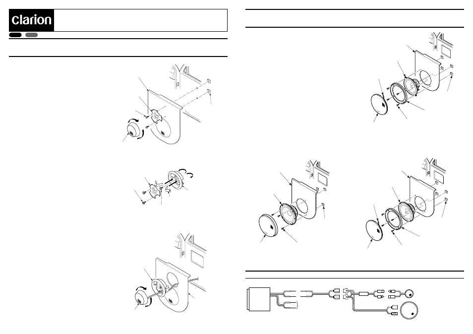
BEISPIEL FÜR EINBAU EINES MITTELBEREICH/TIEFTONLAUTSPRECHERS
ESEMPIO DI INSTALLAZONE DEL MEDIAGAMMA/WOOFER
Türleiste
Copertura della portiera
Gitter
Griglia
Lautsprecher
Diffusore
4-Befestigungschrauben
4 viti di montaggio
Stanznetz
Retina di foratura
U-Typ-Gummi
Gomma di tipo U
4-Schnellmuttern
4 dadi rapidi
Abbildung 5 /
Figura 5
Abbildung 6 /
Figura 6
SRS1725
SRS1625
SRS1325
BEISPIEL FÜR EINBAU EINES HOCHTONLAUTSPRECHERS
ESEMPIO DI INSTALLAZIONE DEL TWEETER
1. Die Türleiste entfernen und dann mittels der Schablone 1 die
Löcher für die Schrauben und Lautsprecherleitungen öffnen.
2. Die Befestigung an der Türleiste anbringen. (Abbildung 1)
3. Für Befestigung den Lautsprecher auf die Befestigung drücken
und drehen.
1. Rimuovere la copertura della portiera, poi usare la maschera 1
per aprire fori per le viti e i cavi diffusore.
2. Installare la staffa sulla copertura della portiera.
3. Premere e ruotare il diffusore sulla staffa per fissarlo.
1. Die beiden Hebelarme vollständig in die mittleren Löcher des
eingelassenen Abstandhalters einführen. Die Hebelarme mit
der Maschinenschraube sichern.
2. Nach Einbau der Hebelarme, mit den Maschinenschrauben die
Befestigung beim eingelassenen Abstandhalter anbringen.
3. Den eingelassenen Abstandhalter auf der Türleiste anbringen.
Nach Beendigung des Einbaus, den Lautsprecher ein-
schrauben, bis er fest einsitzt.
1. Inserire i due bracci leva a fondo nei fori centrali dello spaziatore
per montaggio incassato. Usare la vite da macchina per assicu-
rare i bracci leva.
2. Dopo aver installato i bracci leva, applicare la staffa allo spazia-
tore per montaggio incassato usando le viti da macchina.
3. Applicare lo spaziatore per montaggio incassato alla copertura
della portiera. Una volta completata l’installazione, avvitare il dif-
fusore fino a che viene fissato in posizione.
Türleiste
Copertura della portiera
Befestigung
Staffa
2-Befestigungschrauben
2 viti di montaggio
Lautsprecher
Diffusore
Abbildung 1 /
Figura 1
2-Schnellmuttern
2 dadi rapidi
Eingelassener Abstandhalter
Spaziatore per montaggio incassato
Abbildung 3 /
Figura 3
Abbildung 2 /
Figura 2
2-Hebelarme
2 bracci leva
2-Maschinenschraube
2 viti da macchina
Maschinenschraube
viti da macchina
Türleiste
Copertura della portiera
Befestigung
Staffa
Lautsprecher
Diffusore
Eingelassener
Abstandhalteraufbau
Insieme dello spaziatore
per montaggio incassato
Italiano
Deutsch
2-Weg-Komponentensystem
Installationsanleitung
Sistema a componenti a 2 vie
Manuale d’lstruzioni
Türleiste
Copertura della portiera
Gitter
Griglia
Lautsprecher
Diffusore
4-Befestigungschrauben
4 viti di montaggio
Stanznetz
Retina di foratura
U-Typ-Gummi
Gomma di tipo U
4-Schnellmuttern
4 dadi rapidi
Abbildung 4 /
Figura 4
Gedruckt in China / Stampato in Cina 2003/8 (D
•
C/
GPE
)
SE-751A/SE-752A/SE-753A