840a class xd integrated amplifier, Balanced audio connections, Azur class xd integrated amplifier 13 – Cambridge Audio 840A User Manual
Page 13
840A Class XD integrated amplifier
Azur Class XD integrated amplifier 13
Balanced audio connections
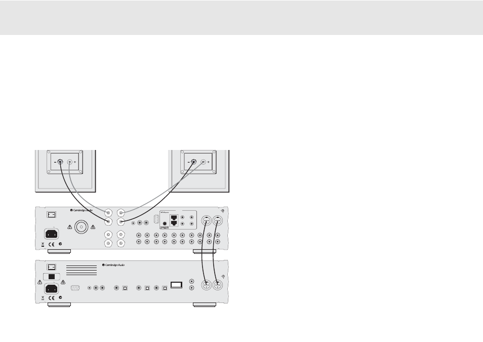
The diagram below shows how to connect the 840A to the Azur 840C
Upsampling CD player using the Balanced Audio inputs via three-pin XLR
connectors (Note: the 840A can also be connected to non-Cambridge
Audio sources with balanced outputs).
Balanced connections in an audio system are designed to reject
electrical noise, from power wiring etc, and also the effects of noise
currents flowing through ground connections. The basic principle of
+
_
+
_
_
Right
Right
Right
Right
+
_
+
Left
Left
Left
Left
Right
Left
Right
Left
IR1
IR2
IR3
IR4
Keypad 1
Keypad 2
Multi-Room
IR Emitter
In
In
Out
Right
Left
Right
Left
Preamp Out
Tape Out
Tape In
Input 7
Input 6
Input 5
Input 4
Input 3
Input 2
Input 1
Preamp Out
Tape Out
Tape In
Input 7
Input 6
Input 5
Input 4
Input 3
Input 2
Input 1
Loudspeaker Terminals
Impedance 4 - 8 ohms
Input 1 Balanced Audio
RS232C
Control Bus
Power
PSU
In
International Patent Pending
LeisureTech Electronics Pty Ltd
Please ensure that loudspeaker terminals are fully tightened
Veuillez s'assurer que les bornes de l'enceinte sont entièrement serrées
B
B
A
A
GND
www.cambridge-audio.com
Manufactured in an ISO9002 approved facility
Power AC
Designed in London, England
Caution Risk of electric shock. Do not open.
Avis Risque de choc electrique. Ne pas ouvrir.
Achtung Vorm öffnen des gërates. Netzstecker ziehen.
azur 840A Class XD
™
Integrated Amplifier
Power Rating
: 230V AC ~ 50Hz
Max Power Consumption
: 800W
On
Off
N2409
Digital Outputs
Power AC
Designed in London, England
azur 840C Upsampling Compact Disc Player
Max Power Consumption
: 40W
www.cambridge-audio.com
RS232C
IR Emitter
In
In
Out
Control Bus
S/P DIF
Co-axial
Toslink
Optical
Digital Input 1
Right
Left
Right
Left
Balanced Audio Out
Unbalanced Audio Out
S/P DIF
Co-axial
Toslink
Optical
Digital Input 2
S/P DIF
Co-axial
Toslink
Optical
Right
Left
Right
Left
Manufactured in an
ISO9002 approved facility
On
Off
Power
Class 1 Laser Product
Luokan 1 Laserplaite
Klass 1 Laserapparat
Mains Voltage Selector Switch
115V/230V AC~50/60Hz
N2409
Caution Risk of electric shock. Do not open.
Avis Risque de choc electrique. Ne pas ouvrir.
Achtung Vorm öffnen des gërates. Netzstecker ziehen.
GND
balanced interconnection is to get the signal you want by subtraction,
using a three-wire connection. One signal wire (the hot or in-phase)
carries the normal signal, while other (the cold or phase-inverted)
carries an inverted version. The balanced input senses the difference
between the two lines to give the wanted signal. Any noise voltages that
appear identically on both lines (these are called common-mode
signals) are cancelled by the subtraction. An additional advantage is
that the connection effectively carries twice the signal level and so
improves the signal-to-noise ratio.
The 840A and 840C are designed to work at their highest performance
when a balanced interconnect is used; high quality stereo XLR to XLR
interconnects should be used.
8
84
40
0C
C
8
84
40
0AA