Dq series, Dq fan coil specifications, Condensing unit wiring – Vintage Cellars DQ Series Split System User Manual
Page 2: Field wiring, Back of controller connections
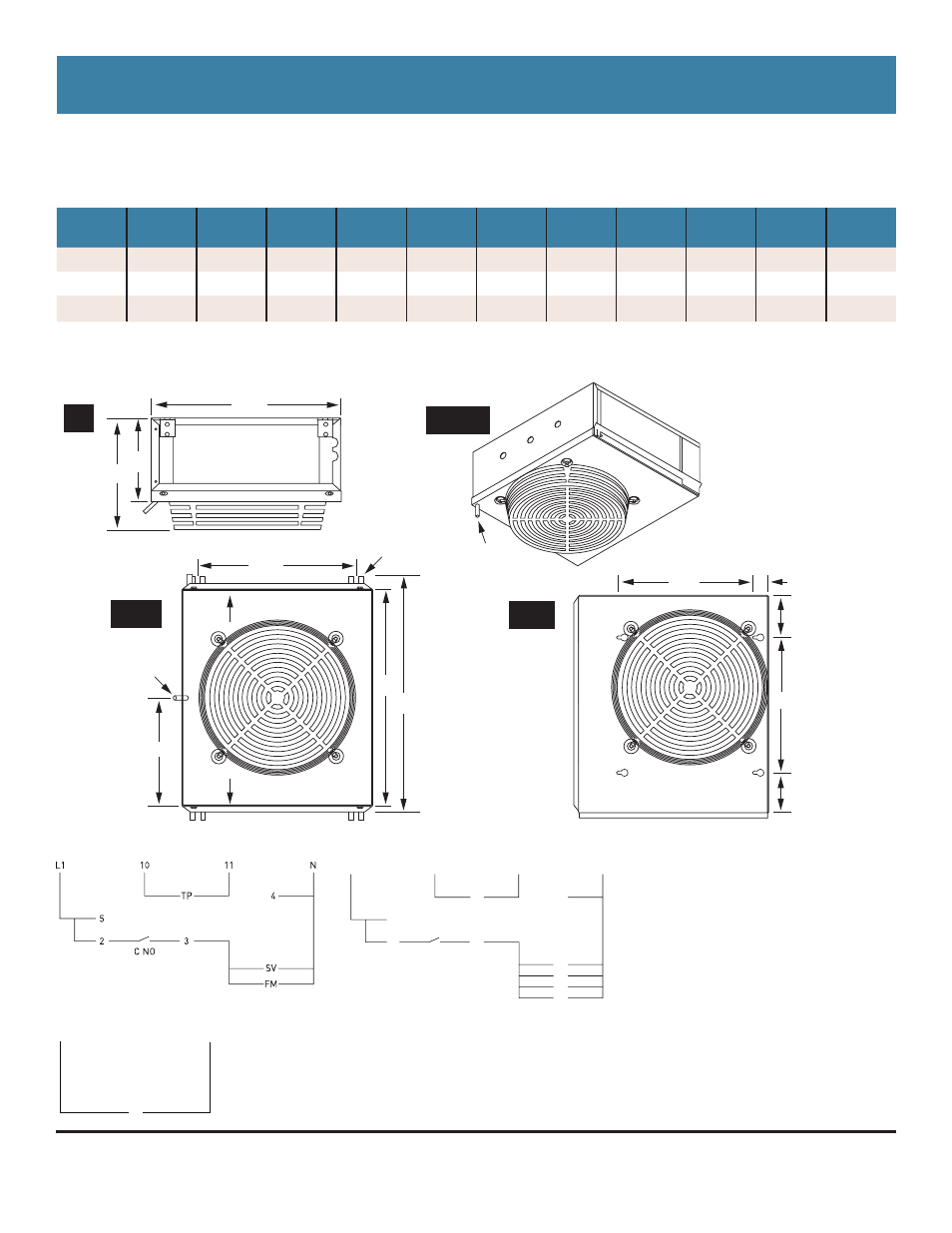
DQ SERIES
DQ Fan Coil Specifications
MODEL
WIDTH
A
B
CFM
FAN DIA MOTOR
AMPS
115 V
LIQUID
SUCTION
DRAIN
APPROX
SHIP WT.
DQ 207
17.5”
7.5”
4.75”
350
10”
16 W
0.06
3/8”
1/2”
3/8”
30
DQ 275
17.5”
9.5”
6.75”
465
12”
16 W
0.06
3/8”
1/2”
3/8”
35
DQ 345
17.5”
10.5”
7.75”
580
12”
16 W
0.06
3/8”
1/2”
3/8”
40
TE Fan Coil Wiring
Single Fan Coil Wiring
Mounting Diagrams
Field Wiring
L1
115 V Line Voltage
N Neutral
SV
Solenoid Valve
FM Fan Motor
TP
Temperature Probe
Back of Controller Connections
10
Temperature Probe
11
Temperature Probe
4 Neutral
5
115V Line Voltage
2
Jumper from 5
3
Switch Leg to Fan Coil
C NO Internal normally open contact
69
73
/
1
&12
)0
69
)0
4
Condensing Unit Wiring
L1
CU
N
17
1
/
2
”
A
B
Side
View
Hangers
with
1
/
2
” slot
3
/
8
” OD drain
14
3
/
4
”
20”
23”
10”
Airflow
Airflow
Standard
Unit
3
/
8
” OD drain
Corner Unit
3-D View
12
1
/
2
”
12
1
/
2
”
1
3
/
8
”
3
3
/
4
”
3
3
/
4
”
Corner
Unit
• Expansion valve and liquid line solenoid valve standard
• Suction line accumulators recommended
April 5, 2012 7:53 PM
US Cellar Systems / 3070 Golden Ave, Long Beach, CA 90806 / www.uscellarsystems.com
(562) 513-3017 phone and fax / [email protected]
Due to continuing engineering improvements, specifications are subject to change without notice.