Vsub, Factory wiring of open loop vfd drive – Tjernlund VSUB Series Universal Blowers for Combustion Air or Draft 8504114 User Manual
Page 11
10
STATIC PRESSURE METHOD TO VERIFY ROTATION:
1. Turn OFF the service switch to all of the heating appli-
ances so they will not run during this test.
2. Adjust the heating appliance balancing baffle(s) or
blast gate(s) to the closed position.
3. Turn the speed adjustment knob on the VFD to the 3:00
o'clock position, Hz_____. Activate the VSUB Blower by
installing a jumper between positions MS3 and MS4 on
the VFD terminal strip. Record the static pressure in the
vent pipe using a manometer or digital pressure gauge
in. W.C. _____. Disrupt power to the VFD and wait 60
seconds before continuing to avoid electrical shock.
4. Locate the two wires within the VFD enclosure that are
connected with pink quick connects. Separate the quick
connects and reconnect the White/Brown lead attached
to the filter board to the previously unconnected lead
from VFD terminated with pink quick connect.
Reestablish power to the VFD.
5. Perform steps 3 & 4 above. Important: VFD must be at
same Hz _____ (speed) as the initial test. The rotation
direction that yielded the higher static pressure is the
correct rotation. If the earlier static pressure result was
the higher pressure result, perform step 4 to reverse the
rotation. Remove jumper from the MS3 and MS4 posi-
tions on the VFD terminal strip.
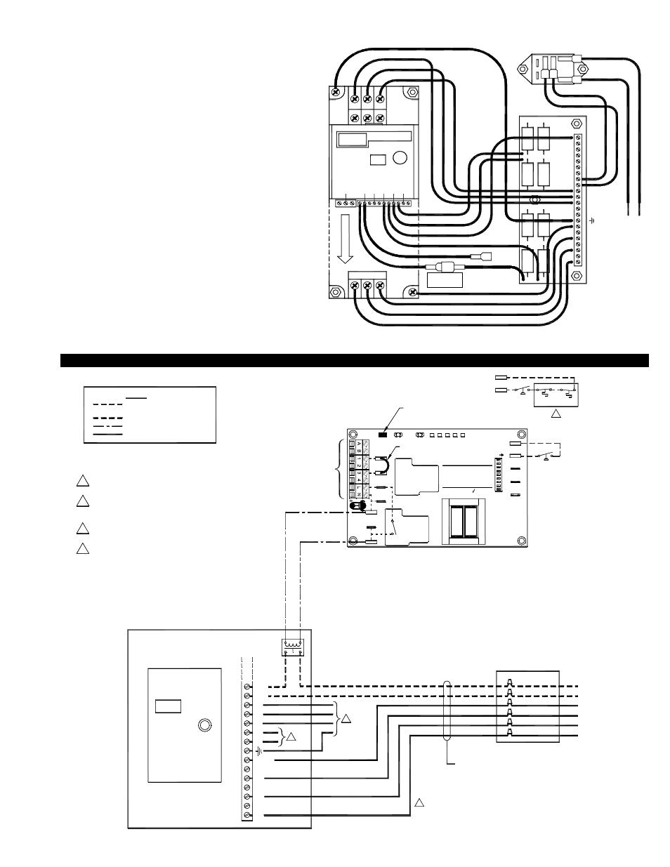
WIRING VSUB FOR A ADJUSTABLE-FIXED SPEED APPLICATION (MANUALLY ADJUSTED WITH AN OPEN LOOP VFD)
WARNING:
IN
C
.
7. For appliance interlock, use UC1 instructions.
"O" means "Open Loop"
VFD- _ _ _ _ _ _ _ O
TJERNLUND DRIVE MODEL
Check motor rotation
(See VFD instructions)
VFD
MGND
M3
M2
M1
MS4
MS3
L3
F1
F2
L2
L1
ADJUST
SPEED
RELAY
Voltage from F1 & F2 is the same as voltage to L1 & L2.
DO NOT run input and output wiring in the same conduit.
All wiring must be in metal conduit (best) or shielded cable.
230 VAC OR 460 VAC
5 VDC BOARD-GENERATED POWER
DO NOT SUPPLY POWER!
115 VAC
NOTES:
FIGURE 8089002 03/23/04
6.
5.
3.
2.
1.
LEGEND:
24 VDC
FOR APPLIANCE INTERLOCK
SEE UC1 INSTRUCTIONS
INFORMATION
100' (30m) @ 460 VAC
All wiring must be in metal conduit
or shielded cable. Maximum length
300' (91m) @ 230 VAC and
BOX AND WHIP
WEATHERPROOF
3
1
ORANGE
BLACK
BLACK
GREEN
BLACK
BLUE
VSUB
will be off if power has been removed from the control.
in personal injury and/or equipment damage. LED #5 (RED)
Remove power to Universal Control when installing, servicing,
or changing dip switch settings. Failure to do this may result
P2
P1
C
G
N
D
F
RED JUMPER POSITION MUST BE THE SAME
AM
BER
GR
EEN
GR
EEN
CALL
INTERLOCK
RELAY
TJ
E
R
N
L
U
N
D
PR
O
D
U
C
T
S
,
9183006
MTR
M
NO
COM
XL
R
XN
N
J1
J2
K2
JUMPER
PRE-PURGE SETTINGS
OPEN PROVER OPTION
POST-PURGE SETTINGS
K1
7
(9)
9
8
(1 - 2)
(3 - 8)
26
5
34
ON
1
AS APPLIANCE INTERLOCK VOLTAGE.
IMPORTANT:
115V
UC1
24V
DRY
LED1
LED3
RE
D
LED5
RE
D
LED4
LED2
FFP-1
PSA-1
4
PSA-1
P1
P2
Verify that the VSUB motor is wired for the output voltage
from the drive. If not correct, severe damage will result.
Verify that the input voltage matches the drive's nameplate
BEFORE applying power or severe damage will result.
4. Use FFP-1 when using VSUB as a combustion air provider.
Auxiliary powered devices at F1 & F2 (e.g. the included
VSUB motor heater) may require a step-down transformer.
2
D P
IMPORTANT:
in the installation manuals.
Perform a safety interlock and operational test as outlined
FIGURE 8084002
M1
M2
M3
MGND
L1
L2
F2
F1
L3
MS4
V1
S2
S1
MS2
MS1
V3
V2
YELLOW
RED
VIOLET
GREEN
BROWN
BLUE
GRAY
WHITE
ORANGE
BLACK
BLACK
BLACK
GREEN / YELLOW
E
X
P
L
O
D
E
D
U/T1 V/T2 W/T3
_
+1
+2
R/L1 S/L2 T/L3
MA
MB
MC S1
S2
S3
S4
S5
SC
FS
FR
FC
AM
AC
WHITE / RED
WHITE / BROWN
MS3
YELLOW
ORANGE
BLACK
WHITE
FACTORY WIRING OF OPEN LOOP VFD DRIVE
PINK QUICK
CONNECT