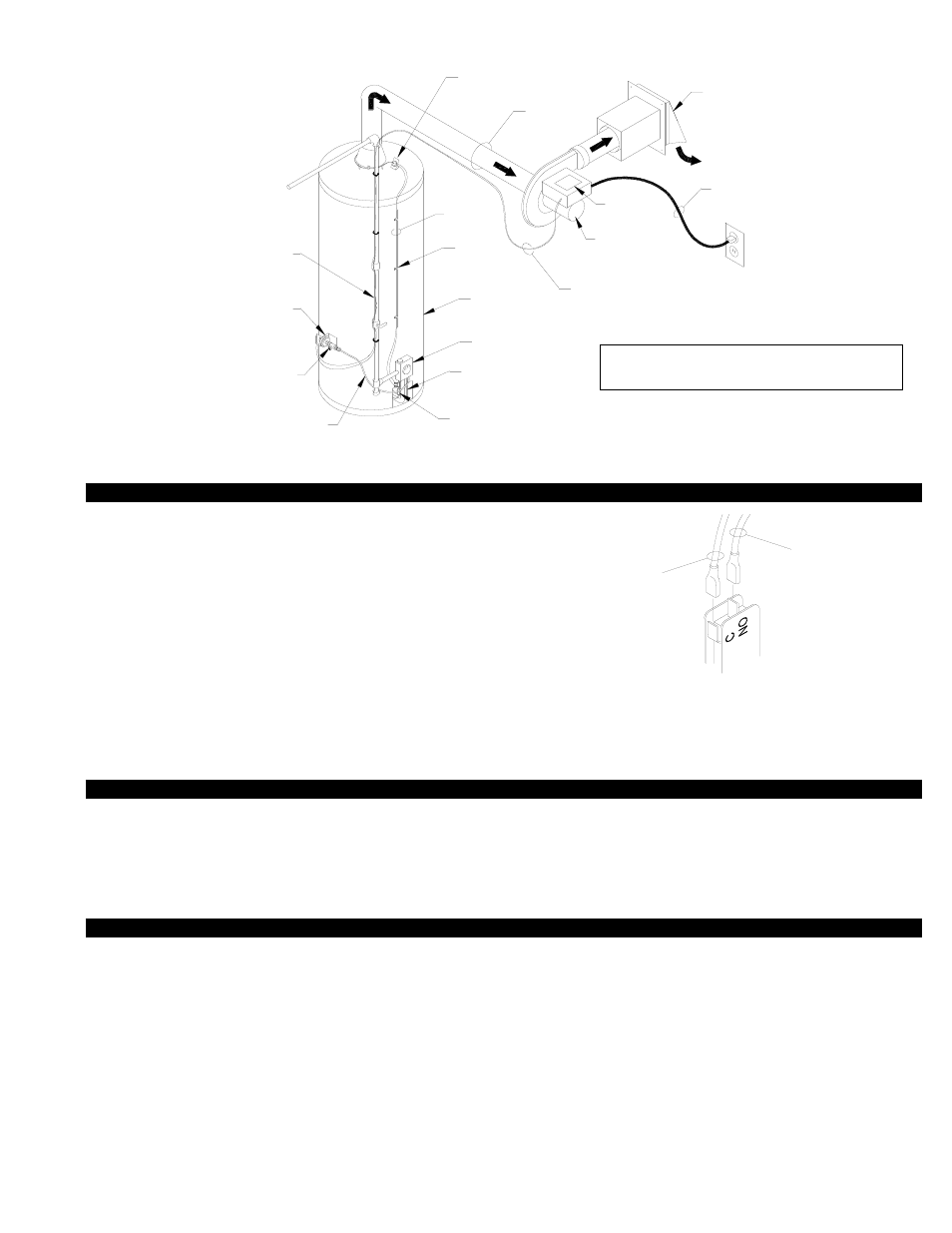
Diagram d, Typical installation – Tjernlund VP-2F, VP-3F Airotronics Timer 8504140 Rev A 11/11 User Manual
Page 9
ACTUATING AND SAFETY CONTROL CIRCUIT CONNECTIONS
1. If not previously completed, push both leads from the Linear Limit
spill switch onto Thermocouple Junction Adapter terminal, (See
Diagram C, Page 5). NOTE: On 750 Millivolt (power pile) heaters,
wire Linear Limit spill switch in series with high limit (ECO) of heater.
2. Push the Red lead from Power Venter 25’ control cable onto the
common on the Gas Pressure Switch, (See Diagram D)
3. Push the Blue lead from the Power Venter 25’ control cable onto
the normally open terminal on the Gas Pressure Switch, (See Diag. D).
4. Plug the power cord from the Power Venter into a grounded 115
VAC outlet. Verify that the outlet is powered through a 15 amp
circuit breaker.
NOTE: The Power Venter may operate for approximately 45 seconds when power is first
established. Wait until the Power Venter shuts off before continuing.
OPERATION CIRCUIT CHECK
1. Place water heater in operation.
A. The Power Venter should operate.
2. Turn gas pilot knob to “pilot”.
B. The Power Venter should continue to operate for approximately 45 seconds to purge the vent system of any residual flue gases.
3. Repeat steps 1 and 2 twice to assure operation.
SAFETY INTERLOCK TEST
IMPORTANT:
The Linear Limit spillage sensing switch must disable the heater in the event of a venting malfunction. The following procedure is
necessary to confirm that the heater is disabled in the event of a venting malfunction.
1. Unplug Power Venter from 115 VAC outlet to disable the Power Venter.
2. Adjust the heater’s thermostat or run hot water until full burner operation occurs. Venter should not run, but burner should fire.
3. Flue gas spillage will emit from the draft hood. Linear Limit spillage sensor should open in less than 3 minutes, extinguishing pilot
light and disabling water heater. If water heater is not disabled, remove call for heat, reposition Limit and repeat steps 1-3.
4. Wait 2-3 minutes for Linear Limit sensing element to cool and push the reset button on Linear Limit spillage sensing switch.
5. Plug Power Venter power cord back into 115 VAC outlet.
6. Re-light pilot following the heater manufacturer’s instructions. Adjust the heater’s thermostat or run hot water until full burner opera-
tion occurs. Power Venter should now be running while burner is firing. Turn thermostat down or hot water off so burner is no
longer firing. Power Venter should continue to run for approximately 45 seconds during the Relay/Timer post-purge cycle.
8
BLUE WIRE FROM
VP-2F / VP-3F
RED WIRE FROM
GAS PRESSURE
SWITCH
CONTROL CABLE
CONTROL CABLE
VP-2F / VP-3F
8050012 11/30/11
NOTE: The installer must ensure that
all electrical connections are tight.
WITH THE ECO OF THE WATER HEATER.
REQUIRED. WIRE THE LINEAR LIMIT IN SERIES
THE THERMOCOUPLE JUNCTION ADAPTER IS NOT
ON 750 MILLIVOLT (POWER PILE) HEATERS
THERMOCOUPLE JUNCTION ADAPTER
PRESSURE TAP
FROM THERMOSTAT
6' LINEAR
LIMIT LEADS
115/1/60
NAMEPLATE
MOTOR
VENTER
POWER
SWITCH
GAS PRESSURE
GAS PRESSURE SWITCH
ALUMINUM TUBING TO
24" LONG 1/4" O.D.
LINE
GAS SUPPLY
BY OTHERS
WATER HEATER
BY OTHERS
THERMOSTAT
LINE
GAS PILOT
8050013 11/30/11
CLIPS
ROUTING
CABLE
THERMOSTAT CABLE
2 WIRE JACKETED
POWER
6 FOOT
BY OTHERS
FLUE PIPE
SWITCH SET AT 185°F
SPILLAGE SENSING
LINEAR LIMIT
GAS PRESSURE
TAP PORT
NOTE:
CORD
TJERNLUND
VENT HOOD
TYPICAL INSTALLATION
DIAGRAM D
NOTE: The installer must install the Power
Venter downstream of the draft hood.