Tjernlund SS2 SideShot with UC1 Universal Control (Version X.02) 8504105 Rev 07/02 User Manual
Page 5
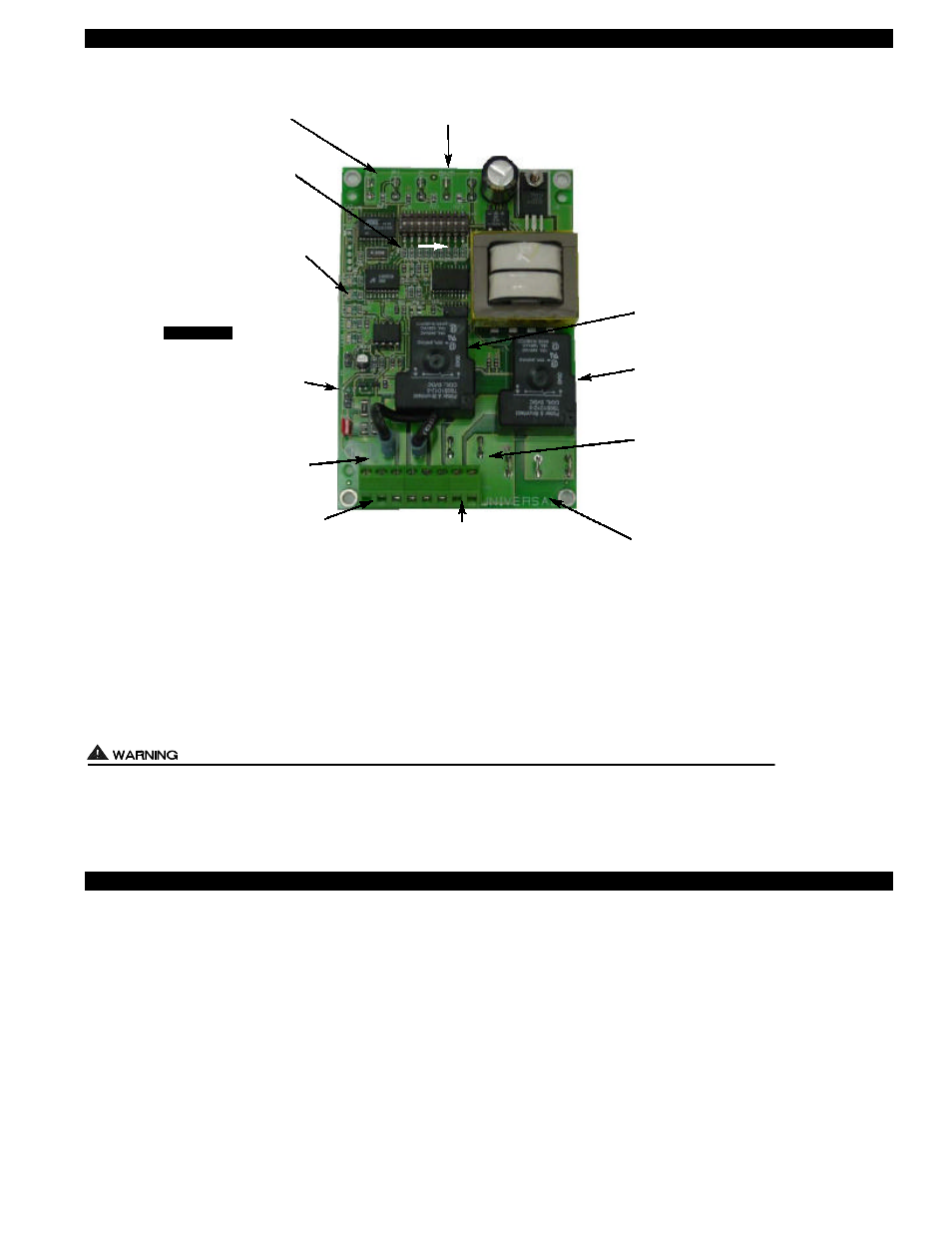
SS2 WITH INTEGRAL UC1 UNIVERSAL CONTROL BOARD FEATURES
# 1.
Power supplied by board. Do not supply power to this area or control damage may result.
# 2. Do not supply power to the appliance interlock block with the call selector in the “DRY” position.
Control damage may result if power is supplied.
# 3. Circuit protection must be provided by the installer. 16 Amps is the maximum current allowed for this device at terminal L.
V
A 15 Amp circuit breaker is recommended.
V
ETI
LED STATUS & FAULT INDICATORS
LED INDICATOR LIGHTS
LED #1 (Amber) Appliance call for heat.
LED #2 (Green) Safety circuit through P1 & P2 (SS2 Limit & Fan Prover) is verified “Open” upon start-up. Burner circuit is
energized with contact closure from terminal 3 to 4. Also verifies SS2 prover & limit are closed during run cycle.
LED #3 (Green) Power switched to SS2 Motor & Cooling Fan from L to MTR & M.
LED #4 (Red)
Status indicator.
LED #5 (Red)
115 VAC power supplied to board. Also used as status indicator.
LED INDICATOR LIGHT STATUS & FAULTS
LED #4 & #5 Flashing Alternately
= Prover start up fault. SS2 Prover contacts “Closed” across P1 & P2 upon appliance call
before SS2 is turned on. Prover status check must be activated, see page 5.
LED #4 & #5 Flashing in Unison
= Fan Prover circuit is “Open” longer than 60 seconds on start-up or 10 seconds during run
cycle. Prover or Limit contacts are not staying “Closed” across P1 & P2 safety circuit.
LED #4 Flashing & #5 on Continuous = System in Pre-Purge. (Pre-Purge options 0, 15, 30, 60 seconds)
LED #5 Flashing & #4 on Continuous = System in Post-Purge. (Post-Purge options 0, 30 seconds or 1, 2, 4, 8, 16 minutes)
IMPORTANT: To reset faults, verify fault by checking the LEDs and then remove call for heat.
4
LED STATUS LIGHTS
See “LED Status & Fault
Indicator Section” for details.
LED 1 (AMBER)
LED 2 (GREEN)
LED 3 (GREEN)
LED 4 (RED)
LED 5 (RED)
DRY
24 V
115 V
J1- J2 CALL
JUMPER
Used when the call signal is
used as the “proven” return
signal to the appliance. See
wiring section for details.
APPLIANCE INTERLOCK
TERMINAL BLOCK (A-B, 1-4)
A - B - Dry Contact call. 3 mA @ 5VDC.
SEE WARNING # 1.
1 - 24 or 115 VAC intercepted call.
IMPORTANT: RED voltage jumper must
match intercepted call voltage.
2 - 24V common or 115V Neutral.
3 - Common terminal to appliance relay con-
tacts. IMPORTANT: J1-J2 jumper routes
call voltage at terminal 1 to 3. Remove
J1-J2 jumper if a different voltage source is
provided to terminal 3.
4 - Normally open terminal of appliance relay.
Will be energized from terminal 3 if safety
circuit is “proven”.
L / N - 115 VAC POWER
SUPPLY BLOCK
115 VAC / 50-60 Hz
Circuit protection provided by installer.
SEE WARNING # 3.
MTR & M LOAD TERMINALS
FROM VENTER MOTOR RELAY
Used to drive SS2 Motor & Cooling fan.
1 HP MAX LOAD across terminals MTR & M / N.
XL / XN AUXILIARY DEVICE
POWER TERMINALS
115 VAC - Maximum of 0.15 Amps.
Only connect to Tjernlund auxiliary devices.
SEE WARNING # 1.
APPLIANCE INTERLOCK
RELAY
1 HP MAX LOAD across
terminals 3 & 4.
VENTER MOTOR RELAY
1 HP MAX LOAD from
terminals L to MTR & M.
APPLIANCE
INTERLOCK
RELAY
VENTER
MOTOR
RELAY
A B 1 2 3 4 L N
J1 J2 XL XN
P1 P2 C GND F
(1 9)
N M MTR
P1 - P2 SAFETY CIRCUIT
TERMINALS
1 mA @ 5VDC.
SEE WARNING # 1.
C, GND, F AUXILIARY DEVICE
COMMUNICATION TERMINALS
2 mA @ 5VDC. For Tjernlund MAC1E or
MAC4E auxiliary devices. SEE WARNING # 1.
APPLIANCE CALL
VOLTAGE SELECTION
Place RED voltage jumper in
proper location based on
appliance call interlock volt-
age. SEE WARNING # 2.
IMPORTANT
DIP SWITCH SETTINGS
Pre-Purge (1-2)
Post-Purge (3-8)
Prover status check (9)
See “Pre / Post Purge &
Prover Status Check Dip
Switch Settings”.