Tjernlund SS2 SideShot with UC1 Universal Control (Version X.04) 8504105 Rev B 05/03 User Manual
Page 11
10
ELECTRICAL WIRING
All wiring from the SS2 to the appliance must be appropriate Class 1 wiring as follows: installed in rigid metal conduit, intermediate metal conduit,
rigid non-metallic conduit, electrical metallic tubing, Type MI Cable, Type MC Cable, or be otherwise suitably protected from physical damage.
SS2 SEQUENCE OF OPERATION WITH INTEGRAL UC1 UNIVERSAL CONTROL AND 24 VAC OR 115 VAC HEATER CONTROL CIRCUIT:
Control signal from thermostat, aquastat or primary control is intercepted and routed to terminal “1” on UC1 terminal strip. When terminal “1” is ener-
gized with either 24 VAC or 115 VAC, the Venter motor is energized. After draft is established, the Fan Proving Switch closes within 5 to 10 seconds
energizing terminal “4”, which completes the circuit allowing burner to fire. NOTE: If a Venter pre-purge is selected, the burner will not fire until the pre-
purge time is finished. The Venter will continue to run after the burner has finished firing for the set post-purge time cycle. The UC1 is set for a 2
minute post-purge time period from the factory. See “Pre / Post-Purge Settings” on page 5 for details.
The "1" input terminal on the SideShot can accept either a 24 VAC or 115 VAC control signal. IMPORTANT: The RED voltage jumper must be
positioned based on appliance interlock voltage 24V or 115V. If using the “DRY” contact activation method, use terminals A & B on UC1 control and
position the RED voltage jumper tab in the “DRY” position. IMPORTANT: Only one interlock method (i.e. 24V, 115V or “Dry”) can be used with the
UC1. Multiple appliance interlocks require the use of our MAC-Series multiple appliance controls.
The steps listed under each diagram are intended as a supplement to the diagram. Wiring colors or designations may vary by manufacturer. If you are
unable to wire the SS2 as outlined in these instructions, call Tjernlund’s Customer Service Department toll free at 1-800-255-4208 for assistance.
IMPORTANT: If the call for heat interlock signal or 115 VAC power is removed, the UC1 board will reset and any fault, if present, will be stored in mem-
ory instead of displayed. See page 5, “Checking Memory for Last Fault Code”.
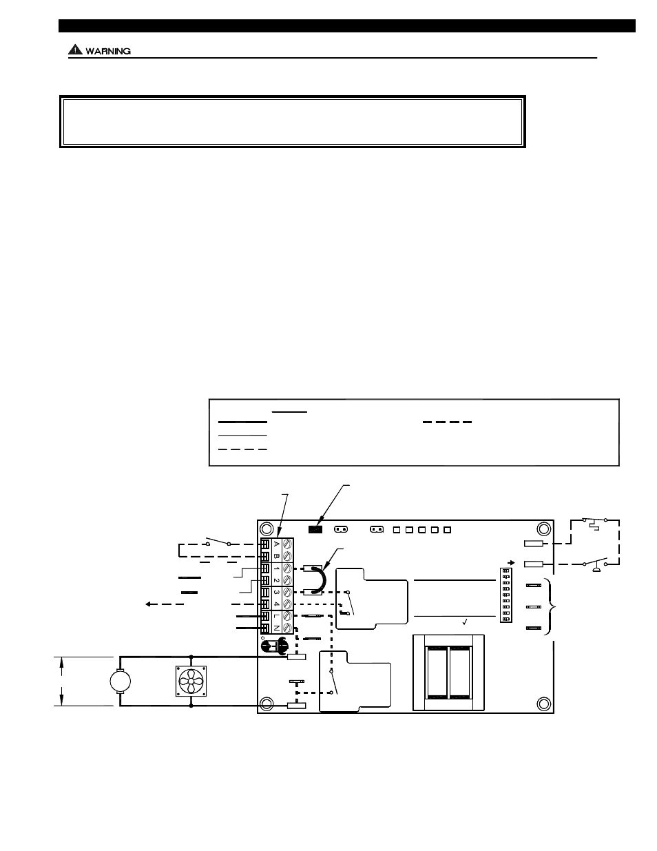
SS2 WITH INTEGRAL UC1 UNIVERSAL CONTROL
(THE SS2 MOTOR, COOLING FAN, LIMIT & PROVER ARE ALL FACTORY PREWIRED)
IMPORTANT: MORE THAN ONE INTERLOCK METHOD MAY BE APPLICABLE
In many cases it is easier to interlock with the thermostat/aquastat portion of the heater control circuit vs. the primary
control portion of the heater control circuit. Review all of the wiring diagram options prior to choosing the best method.
IMPORTANT:
RED JUMPER POSITION MUST BE THE SAME
AS APPLIANCE INTERLOCK VOLTAGE.
CALL
RELAY
INTERLOCK
COMMON
NEUTRAL
PRODUCTS,
INC.
1 H.P. MAX @ 115 VAC
SUPPLY
115 VAC
50/60 Hz
R
TJERNLUND
9183006
NO
MTR
M
MOTOR
RELAY
N
COM
NO
115 VAC
24 VAC
1303961-1
DO NOT SUPPLY VOLTAGE
TO "A" OR "B".
DO NOT SUPPLY POWER!
5 VDC BOARD-GENERATED POWER
HOT
24 VAC
USER-PROVIDED
CALL SWITCH
LINE
OR
"DRY"
OR
115V
J2
COM
24V
DRY
LEGEND:
115 VAC
5
POST-PURGE SETTINGS
FOR TJERNLUND
TO P1, P2, C, GND
AUXILIARY
OR F. DOING SO
WILL DAMAGE THE
CONNECT POWER
OPEN PROVER OPTION
(9)
(3 - 8)
9
7
8
6
CONTROL.
DEVICES. DO NOT
F
GND
ON
LED1
PRE-PURGE SETTINGS
LED5 LED4
LED2
LED3
(1 - 2)
2
4
3
1
C
P1
P2
J1
XL
XN
115 OR 24 VAC FROM CALL JUMPER
OR USER-PROVIDED VOLTAGE
FROM TERMINAL 3 TO 4 WITH CALL
JUMPER REMOVED
K2
K1
APPROVED
MAC1E OR MAC4E
JUMPER
RED
RED
GREEN
GREEN
AMBER
SS2 PROVER
SS2 LIMIT
COOLING
FAN
SS2
SS2
MOTOR
WARNING: Disconnect power supply from the SS2 and heating equipment when making wiring connections and servicing the
SS2. Failure to do so may result in personal injury and/or equipment damage. LED #5 (RED) should be off with
power removed.