Tjernlund SS1 SideShot with UC1 Universal Control (Version X.02) 8504102 Rev 07/02 User Manual
Page 16
15
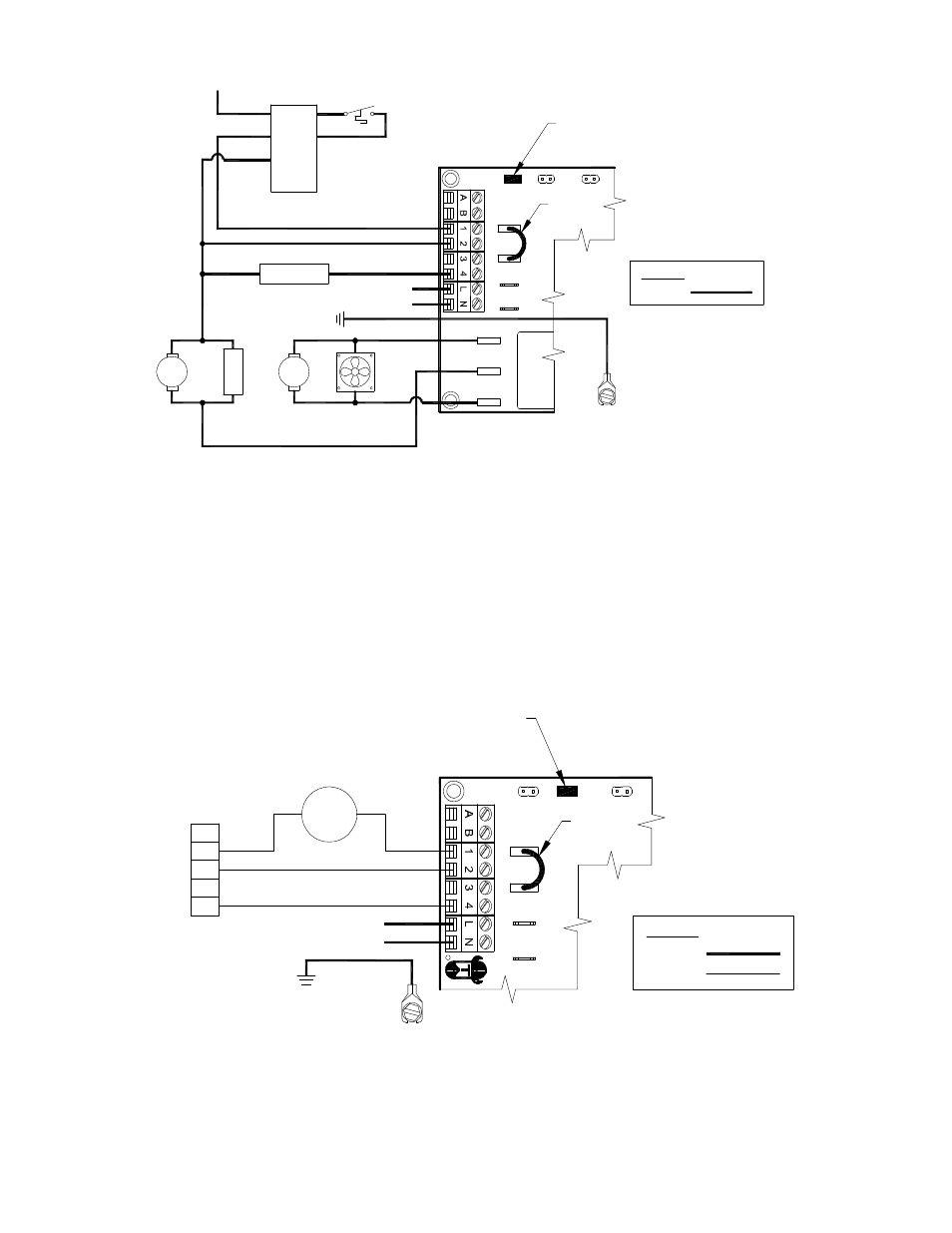
SIDESHOT WITH INTEGRAL UC1 UNIVERSAL CONTROL CONNECTED WITH A HONEYWELL R8184
SERIES OR EQUIVALENT PRIMARY CONTROL AND A BURNER MOTOR POST-PURGE
RED JUMPER POSITION MUST BE THE SAME
AS APPLIANCE INTERLOCK VOLTAGE.
UNIVERSAL CONTROL
XN
BURNER
N
MTR
M
THERMOSTAT
OIL VALVE
W
O
WHITE
ORANGE
B
F
F
T
T
IMPORTANT:
XL
J1
J2
115V
DRY
24V
D/N 9183046-4
115 VAC
LEGEND:
CALL
JUMPER
BLACK
HONEYWELL R8184
SERIES OR EQUIVALENT
L1
SS2
COOLING
SS2
MOTOR
MOTOR
IGNITION
TRANS
50/60 Hz
SUPPLY
115 VAC
SPADE TERMINAL IN ELECTRICAL BOX.
GROUND
CRIMP GROUND WIRE TO GROUNDING
IMPORTANT:
FAN
1. Separate the burner motor wire and ignition transformer from the Orange wire of R8184.
2. Connect the Orange of R8184 to #1 on UC1 terminal block.
3. Connect #2 on UC1 terminal block to White on R8184 or N.
4. Connect the HOT wire of oil solenoid valve to #4 on UC1 terminal block and neutral wire to White or N.
5. Connect burner motor and ignition transformer HOT wires to M terminal on UC1 and neutrals to White or N.
6. Connect 115 VAC supply voltage to L & N terminals on UC1. Installer must supply overload and disconnect protection.
7. Crimp ground wire to grounding spade in SS1 electrical box.
8. Make sure RED voltage jumper on UC1 is on 115V.
SIDESHOT WITH INTEGRAL UC1 UNIVERSAL CONTROL CONNECTED
WITH A SINGLE ZONE 24 VAC THERMOSTAT
XN
R
UNIVERSAL CONTROLLER
THERMOSTAT
G
G
INTERNAL CONTROL
OF FURNACE
W
C
Y
R
R
Y
AS APPLIANCE INTERLOCK VOLTAGE.
RED JUMPER POSITION MUST BE THE SAME
XL
J1
J2
W
DRY
115V
24V
IMPORTANT:
D/N 9183046-5
115 VAC
24 VAC
LEGEND:
CALL
JUMPER
50/60 Hz
SUPPLY
115 VAC
SPADE TERMINAL IN ELECTRICAL BOX.
GROUND
CRIMP GROUND WIRE TO GROUNDING
IMPORTANT:
1. Connect W from t-stat to #1 on terminal block of UC1.
2. Connect #2 on UC1 terminal block to C on internal control terminal strip of furnace/boiler.
3. Connect #4 on UC1 terminal block to W on internal control terminal strip of furnace/boiler.
4. Connect 115 VAC supply voltage to L & N terminals on UC1. Installer must supply overload and disconnect protection.
5. Crimp ground wire to grounding spade in SS1 electrical box.
6. Make sure RED voltage jumper on UC1 is on 24V.