Tjernlund SS1 SideShot with UC1 Universal Control (Version X.04) 8504102 Rev C 02/04 User Manual
Page 18
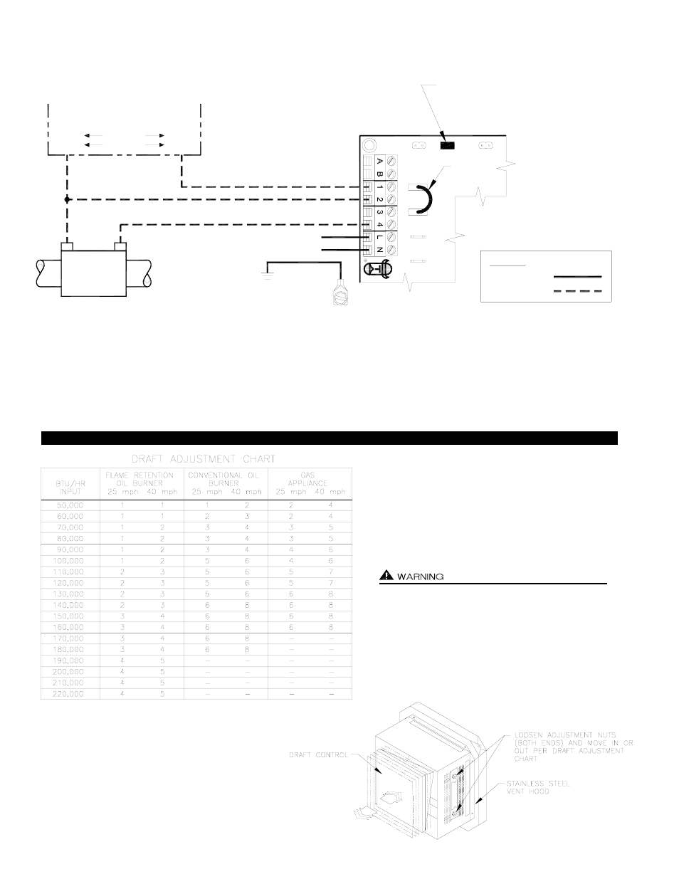
DRAFT ADJUSTMENT PROCEDURE
17
SIDESHOT WITH INTEGRAL UC1 UNIVERSAL CONTROL CONNECTED
WITH A 24 OR 115 VAC STANDING PILOT
115V
24V
DRY
OF FURNACE/BOILER
INTERNAL CONTROLS
24V OR 115V GAS VALVE
HOT
COM
B2
COM
TR
Aquastat
T-stat
TH
HOT
B1
XL
U
N
IVER
SAL C
O
N
T
R
O
LLER
XN
J1
J2
D/N 9183046-1
24 OR 115 VAC
LEGEND:
CALL
JUMPER
115 VAC
50/60 Hz
SUPPLY
115 VAC
SPADE TERMINAL IN ELECTRICAL BOX.
GROUND
CRIMP GROUND WIRE TO GROUNDING
IMPORTANT:
RED JUMPER POSITION MUST BE THE SAME
AS APPLIANCE INTERLOCK VOLTAGE.
IMPORTANT:
1. Remove the wire on TH or HOT of gas valve and connect it on #1 on UC1 terminal block.
2. Connect #2 on UC1 terminal block to TR or Common.
3. Connect #4 on UC1 terminal block to TH or HOT on gas valve.
4. Connect 115 VAC supply voltage to L & N terminals on UC1. Installer must supply overload and disconnect protection.
5. Crimp ground wire to grounding spade in SS1 electrical box.
6. Make sure RED voltage jumper on UC1 is on 24V or 115V depending on control voltage.
NOTE: If burner primary control goes out on lockout, the SideShot will continue to run as long as a call for heat is present.
NOTES: All draft adjustments are approximate. This
chart is to be used for initial draft adjustment only.
Subsequent draft adjustments may be required to com-
pensate for various field conditions: wind, vent pipe
resistance, building pressure, multiple appliances, etc.
BTU/HR input ratings assume 30% or less excess air
for flame retention burners and 50% to 100% excess
air for conventional oil burners.
Do not exceed the recommended BTU/HR input range
of the SideShot.
Under no circumstances shall the minimum draft
adjustment be used for the larger input range of this
product.
Improper draft adjustment may result in the dispersion
of flue products/carbon monoxide into the building interior.
DIAGRAM P