Tjernlund GPAK-1TR 8504047 Rev B 06/14 User Manual
Page 6
VENT HOOD INSTALLATION
1. Attach the Vent Hood template (Page 14) to the interior of the wall the vent hood will be penetrating.
2. Ensure that proposed vent termination clearances are met before attempting to cut opening through exterior wall.
3. Verify that wall penetration will not come in contact with concealed wiring or plumbing. Using a 1/2” drill bit, drill two pilot holes
where noted on the template. The drill bit must be long enough to penetrate to the building exterior.
4. Attach the template to the building exterior aligning the pilot holes on the template with the pilot holes drilled in step 3.
5. Using a reciprocating saw, cut an opening through the building siding, wall board, etc., following the appropriate lines of the template.
6. Slide the vent hood through the opening and fasten to exterior wall using provided screws.
7. Once Power Venter and vent pipe is completely installed and secured, apply a bead of caulk between Vent Hood flange and
exterior of building.
POWER VENTER INSTALLATION
CODE REQUIREMENTS
The Power Venter installation must be done in accordance with the following requirements from the latest Edition of the National Fuel
Gas Code (NFPA #54):
• Design and install All portions of the vent system under positive pressure during operation (on the outlet side of Power Venter) so
as to prevent leakage of flue or vent gases into the building,
• The furnace vent must enter the inlet side of the Power Venter.
• Make provision to interlock the appliance(s) to prevent the flow of gas to the main burners when the draft system is not performing
so as to satisfy the operating requirements of the equipment for safe performance. (See electrical section of this manual for details.)
INSTALLER NOTES
1. Use double wall venting materials only.
2. All vent pipe and reducers must be supplied by the installer and are available from your heating wholesaler.
3. The maximum vent length is 30 feet with a maximum of three 90
O
elbows.
4. All vent pipe and reducers must be supplied by the installer and are available from your heating wholesaler.
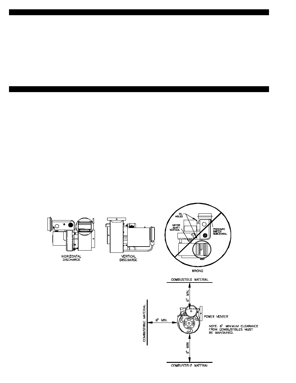
5. The Power Venter may be mounted in any position as long as the shaft of the motor remains horizontal, to prevent motor bearing
wear and to ensure proper Fan Proving Switch operation, (See Diagram A).
6. All furnaces have a 3” flue connection as shipped from the
factory. Use 4” pipe and use a 3” to 4” transition at the
furnace.
7. The Power Venter housing is single wall, a 6 inch clearance
to combustible materials must be maintained, (See Diagram B).
5
DIAGRAM A
DIAGRAM B