Tjernlund UC1 Universal Control (Version X.04) 8504107 Rev C 02/04 User Manual
Page 8
7
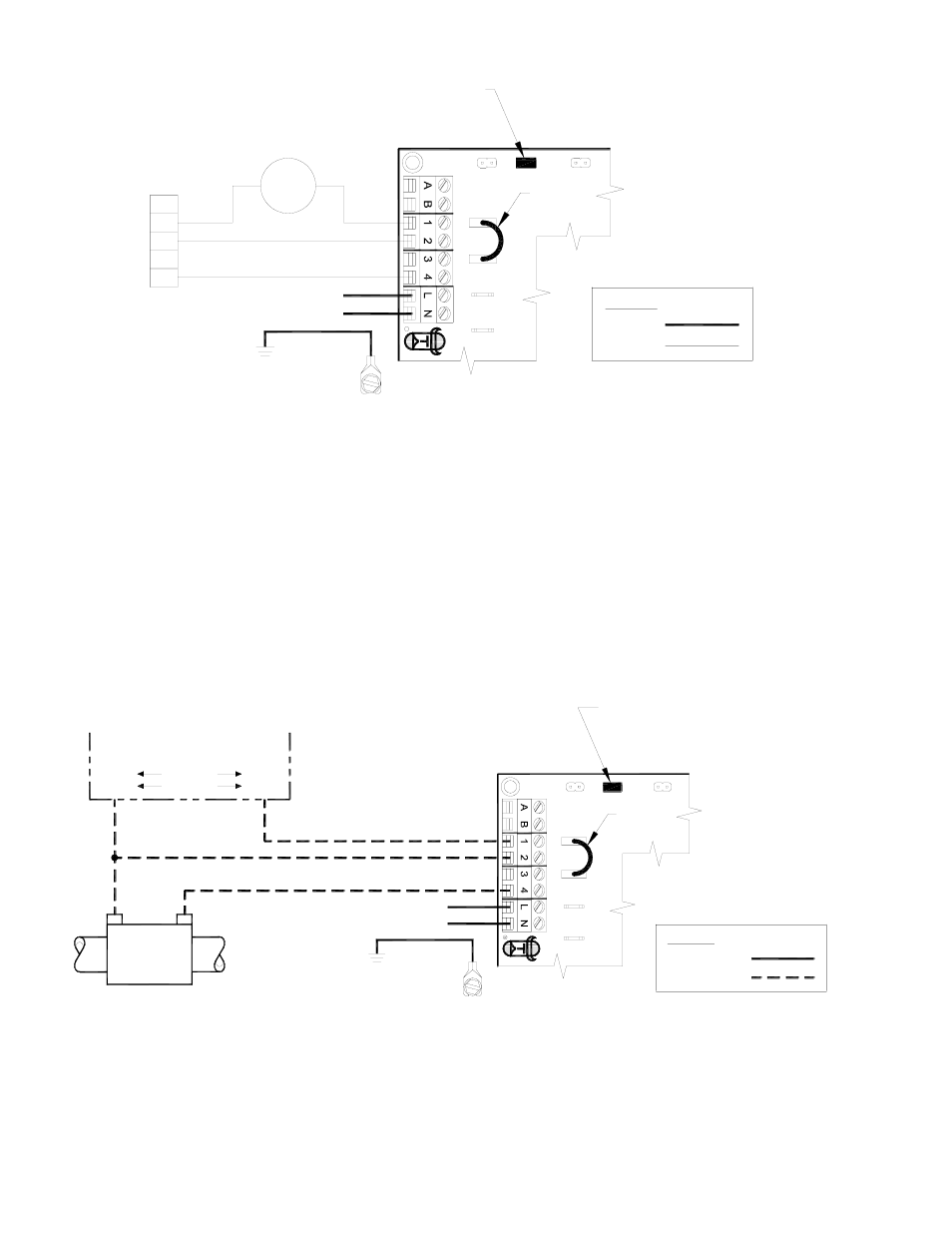
UC1 UNIVERSAL CONTROL CONNECTED WITH A SINGLE ZONE 24 VAC THERMOSTAT
XN
R
U
N
IVER
SAL C
O
N
T
R
O
LLER
THERMOSTAT
G
G
INTERNAL CONTROL
OF FURNACE
W
C
Y
R
R
Y
AS APPLIANCE INTERLOCK VOLTAGE.
RED JUMPER POSITION MUST BE THE SAME
XL
J1
J2
W
DRY
115V
24V
IMPORTANT:
D/N 9183046-5
115 VAC
24 VAC
LEGEND:
CALL
JUMPER
50/60 Hz
SUPPLY
115 VAC
SPADE TERMINAL IN ELECTRICAL BOX.
GROUND
CRIMP GROUND WIRE TO GROUNDING
IMPORTANT:
1. Connect W from t-stat to #1 on terminal block of UC1.
2. Connect #2 on UC1 terminal block to C on internal control terminal strip of furnace/boiler.
3. Connect #4 on UC1 terminal block to W on internal control terminal strip of furnace/boiler.
4. Make sure RED voltage jumper on UC1 is on 24V.
5. Connect 115 VAC supply voltage to L & N terminals on UC1. Crimp Ground wire to grounding spade terminal in UC1.
Important: Installer must supply overload and disconnect protection.
6. If not previously completed, connect ground from UC1 whip to Venter ground. Connect Black and White leads from UC1 whip
to Venter motor leads. Connect Blue and Yellow leads from UC1 whip to Fan Prover switch. Prover Leads are not polarity sensitive.
NOTE: If burner safety control goes out on lockout, the Venter will continue to run as long as a call for heat is present.
UC1 UNIVERSAL CONTROL CONNECTED WITH A 24 OR 115 VAC STANDING PILOT
115V
24V
DRY
OF FURNACE/BOILER
INTERNAL CONTROLS
24V OR 115V GAS VALVE
HOT
COM
B2
COM
TR
Aquastat
T-stat
TH
HOT
B1
XL
U
N
IVER
SAL C
O
N
T
R
O
LLER
XN
J1
J2
D/N 9183046-1
24 OR 115 VAC
LEGEND:
CALL
JUMPER
115 VAC
50/60 Hz
SUPPLY
115 VAC
SPADE TERMINAL IN ELECTRICAL BOX.
GROUND
CRIMP GROUND WIRE TO GROUNDING
IMPORTANT:
RED JUMPER POSITION MUST BE THE SAME
AS APPLIANCE INTERLOCK VOLTAGE.
IMPORTANT:
1. Remove the wire on TH or HOT of gas valve and connect it on #1 on UC1 terminal block.
2. Connect #2 on UC1 terminal block to TR or Common.
3. Connect #4 on UC1 terminal block to TH or HOT on gas valve.
4. Make sure RED voltage jumper on UC1 is on 24V or 115V depending on control voltage.
5. Connect 115 VAC supply voltage to L & N terminals on UC1. Crimp Ground wire to grounding spade terminal in UC1.
Important: Installer must supply overload and disconnect protection.
6. If not previously completed, connect ground from UC1 whip to Venter ground. Connect Black and White leads from UC1 whip
to Venter motor leads. Connect Blue and Yellow leads from UC1 whip to Fan Prover switch. Prover Leads are not polarity sensitive.