Mac4e, Uni versal control, Mac4 e control – Tjernlund MAC4E Control Version F (Compatible with UC1 Control) 8504112 Rev B 08/05 User Manual
Page 2
C24V
DRY3
AMBER
LED7
D115V
D24V
DRY4
K2
INTERLOCK
RELAY
K3
K1
DRY2
RELAY
BLUE
APPL
IANCE 2
LED3
AMBER
LED4
B115V B24V
N
G
G R
E
E
CO
NDU
IT
24" F
LEX
A
I
E
T
K
C
W H
B L
pos
t-
purge s
et
tings
+
s
af
et
y c
irc
ui
t c
onnec
tions
are i
n t
he Uni
vers
al
Cont
rol
.
T
hi
s dev
ic
e m
us
t be c
onnec
ted t
o a Tj
ernl
und Uni
vers
al
Cont
rol
. A
ll pre &
Rem
ov
e power t
o Uni
vers
al
Cont
rol
and al
l c
onnec
ted appl
ianc
es
when
in
st
al
ling or s
erv
ic
ing t
he M
A
C4E
. F
ai
lu
re t
o do s
o m
ay
res
ul
t i
n pers
onal
WARNING:
NOT
E
:
UNI
VERSAL CONTROL
BLUE
LE
D
2
PR
E-
PU
RG
E SE
TTI
N
G
S
OP
E
N
P
R
OV
E
R
OP
T
ION
PO
ST-
P
UR
G
E
S
E
TTI
N
G
S
V
E
N
T
E
R
/ I
NDUCE
R
1 H
.P
. M
A
X
@
115 V
A
C
MO
T
O
R
N
G
E E
R
TJERNLUND
INC.
PRODUCTS,
MTR
W
M
N
L
H
TC EK
IA
B
K2
APPR
OVED
50/
60 H
z
115 VAC
SU
PPLY
R
D
O
N
O
T
SU
PPLY VOLT
AGE
T
O
"A
" O
R
"B
".
GREEN
RED
RED
CA
LL
JU
M
PER
IN
T
E
R
LOC
K
XN
XL
NO
J1
J2
CO
M
K1
RE
LA
Y
DRY
115V
24V
LE
D
5
LE
D
3
LE
D
4
Y
R
P/
N
1303963B
D
E
AMBER
P2
(9
)
(3
- 8
)
F
8 9
6 7
GND
(1
- 2
)
1
4 5
3
2
C
ON
P1
L
O
G R A
E T
I
V
PR
OVER
LE
D
1
B
urner c
irc
ui
t i
s energi
zed wi
th
c
ont
ac
t c
los
ure f
rom
te
rm
inal
3 t
o t
erm
inal
4.
S
af
et
y c
irc
ui
t t
hrough Uni
vers
al
Cont
rol
P
1 &
P
2 F
an P
rov
er i
s v
eri
fied "Open" upon s
tart
up.
A
ppl
ianc
e c
al
l f
or heat
.
L
E
D S
T
AT
US
INDICAT
O
R
L
IG
H
T
S
LE
D #2 (B
lue)
LE
D #1 (A
m
ber)
AS APPLIAN
C
E IN
T
E
R
LOC
K VOLT
AGE.
R
E
D
J
U
M
PER
POSIT
ION
M
U
ST
BE T
H
E SAM
E
IM
P
O
R
T
ANT:
LED
POWER
RED
24 O
R
115 VAC
APPR
OVED
C
A
LL BAC
K T
O
H
EAT
ER
IN
T
E
R
C
E
P
T
E
D
C
A
LL
CO
MMO
N
O
R
NE
UT
RA
L
24 O
R
115 VAC
IN
T
E
R
C
EPT
ED
C
A
LL F
O
R
H
EAT
5 V
D
C B
O
A
R
D-
G
E
NE
RA
TE
D P
O
W
E
R
D
O
N
O
T
SU
PPLY POWER
!
115 VAC
LE
G
E
ND:
T
E
R
M
IN
AL
2
:
T
E
R
M
IN
AL
1
:
T
E
R
M
IN
AL
4
:
LE
D6
U
SER
-P
R
O
VID
E
D
C
A
LL SWI
T
C
H
"DR
Y
"
OR
C
O
MMO
N /
LI
NE
/ HO
T
NE
UTR
A
L
IN
T
E
R
-
H
EAT
C
A
LL F
O
R
C
EPT
ED
properl
y pos
iti
oned.
se
le
ct
ion j
um
per
E
ac
h appl
ianc
e
U
niv
er
sa
l C
on
tr
ol.
in
te
rlo
cke
d with
th
e
to
eac
h A
- B
, 1 - 4
its
red v
ol
tage
MAC
4E mu
st
h
av
e
te
rm
inal
s
tri
p are
A
ppl
ianc
e i
nt
erl
oc
ks
the s
am
e as
on t
he
M
AC4E
in
ju
ry
and/
or equi
pm
ent
dam
age.
LE
D #9 (RE
D
) on t
he M
A
C4E
s
houl
d
APPL
IANCE 1
INTERLOCK
MAC4
E CONTROL
not
be on i
f power has
been rem
ov
ed.
RELAY
INTERLOCK
APPL
IANCE 3
BLUE
LED5
AMBER
LED6
C115V
OPTIONAL DAISY CHAIN CONNECTIONS
INTERLOCK
RELAY
R
R
APPL
IANCE 4
BLUE
LED8
F
R
C2
C
GND
Y
A
O L E T
V
E
I
D
GR
EEN
VIOL
ET
F2
GND
N
L
BLK
TO ADDITIONAL MAC4E
K4
POWER
LED9 - RED
DRY1
GR
Y
RE
D
BLUE
LED2
A115V A24V
L
N
AMBER
LED1
WH
T
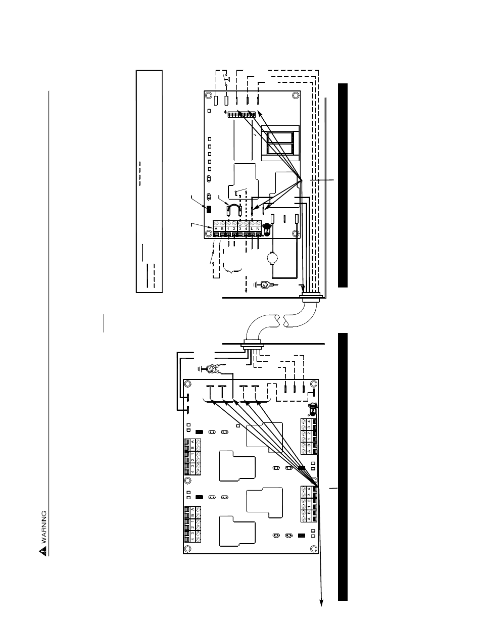
CONNECTIONS FROM MAC4E TO UC1 UNIVERSAL CONTROL
1.
Connect Black from MAC4E whip to XL on UC1.
2.
Connect White from MAC4E whip to XN on UC1.
3.
Connect Green from MAC4E whip to ground screw in UC1.
4.
Connect Gray from MAC4E whip to GND on UC1.
5.
Connect Red from MAC4E whip to F on UC1.
6.
Connect Violet from MAC4E whip to C on UC1.
DAISY CHAIN CONNECTIONS FOR MULTIPLE MAC4E’S CONNECTED TOGETHER
IMPORTANT:
VENTING MULTIPLE HEATERS WITH A SINGLE FIXED SPEED VENTER /
INDUCER MAY REQUIRE TJERNLUND ABD-SERIES BALANCING BAFFLES. FOR INSTAL-
LATIONS REQUIRING MORE THAN ONE MAC4E INTERLOCK, WE RECOMMEND THAT
OUR TECH SERVICE DEPT. BE CONTACTED AT 1-800-255-4208.
1.
Connect White from second MAC4E whip to N on MAC4E connected to UC1.
2.
Connect Black from second MAC4E whip to L on MAC4E connected to UC1.
3.
Connect Green from second MAC4E whip to ground screw in MAC4E connected to UC1.
4.
Connect Red from second MAC4E whip to F2 on MAC4E connected to UC1.
5.
Connect Gray from second MAC4E whip to GND on MAC4E connected to UC1.
6.
Connect Violet from second MAC4E whip to C2 on MAC4E connected to UC1.
TO 2ND MAC4E WHIP
MAC4E WIRING CONNECTIONS WITH UC1 UNIVERSAL CONTROL
Remove power to UC1 and heating equipment when making connections from the MAC4E to the UC1 or installing, servicing or changin
g dip switch settings in the UC1.
Failure to do so may result in personal injury and/or equipment damage.
The Power LED (RED) on UC1 or any LED’s on UC1 or MAC4E
should not be on.
See UC1 Universal Control wiring section of Venter or UC1 instructions for 24 VAC, 115 VAC or Millivolt (Dry Contact)
appliance interlock diagrams. The MAC4E and UC1 Universal Control appliance interlock steps and diagrams are identical.
IMPORTANT:
Venter Fan Prover must be wired to P1 & P2 safety circuit in UC1. Do not
supply power to P1 & P2 or damage will result.
The MAC4E contains four appliance
interlock blocks which are identical. Each appliance interlocked with the MAC4E and UC1 must have the Red voltage jumper on th
e proper 115V, 24V or DRY position based
on appliance interlock voltage.