Thetford EV704D Series User Manual
Page 6
Important Points Regarding Battery-Powered
Sources
The dual battery switch or battery isolator is an important compo-
nent as it permits the alternator or generator to charge both the
accessory battery and the vehicle battery during operation of the
vehicle engine. However, it limits the current draw of the DC appli-
ances to the accessory battery source when the engine or vehicle
is idle or stopped. Thus it assures that the vehicle battery is fully
charged for starting the engine. The batteries referred to in Figure
3 are two 6 volt golf cart batteries connected in series to provide
12 volts. Golf cart batteries are suggested for the following rea-
sons:
1. Larger plate construction.
2. Deep draw characteristics.
3. High ampere-hour rating.
The standard golf cart battery has a rating of approximately 185-
205 ampere-hours. When two of these batteries are connected in
series, the result is 12 volt DC at 185 or 205 ampere-hour capac-
ity.
The DC supply to the refrigerator is connected to the negative
post of one battery and to the positive post of the other battery.
The power converter or solid state battery charger shown in Fig-
ure 3 is an essential item for battery-operated systems.
The converter is operated on 120 volt AC and should have an
output rating of 12.6-l4.5 volts DC at approximately 20-50 ampere
capacity. During 120 volt operation, the converter is used to
charge the batteries and to operate the DC appliances. It has the
capacity to operate items such as lighting, water pumps, exhaust
fans, and sanitary facilities while maintaining or charging the bat-
teries. Charging rate varies from 5-20 amperes per hour.
The Norcold dual voltage refrigerator automatically switches from
AC to DC or from DC to AC. When a power supply of 120 volts
AC is connected to the vehicle, the voltage selection relay is ener-
gized and disconnects the unit from DC operation. This unique
feature assures 120 volt operation when available and permits the
power converter to concentrate it’s charging facilities to the batter-
ies or to other DC appliances.
When the AC supply is disconnected, the refrigerator automat-
ically reverts to DC operation. Setting the On-Off switch to the
"OFF" position will prevent operation on AC or DC.
The following are suggestions for efficient operation of the refrig-
erator:
1. The thermostat dial is numbered from 1 through 5, with the
number 5 setting the maximum coldest position. In order to
conserve battery power, it is advisable to set the thermostat
dial at the lowest setting that will provide adequate refrigera-
tion. This practice will reduce the running time of the refrig-
erator and draw less current from the battery. A setting of 2
or 3 is a normal position.
2. Always operate the refrigerator on 120 volts AC when avail-
able, especially during initial start-up or pull-down cycle of
the refrigerator. Depending upon the ambient temperature,
the initial start-up may require 1-2 hours of continuous op-
eration before refrigerator temperature are attained and unit
cycling begins.
3. Never employ "quick-chargers" to the battery unless the On-
Off switch is set to the "OFF" position or the 12-volt DC
leads to the refrigerator are disconnected. Possible inverter
damage will occur if the high voltage of "quick chargers" is
permitted to energize the DC circuits of the inverter.
4. The use of a commercial 12-volt DC to 120-volt DC solid
state inverter, converter, gasoline or belt-driven generator
with 120 volt AC output is not recommended for operating
the refrigerator unless the manufacture of the foremen-
tioned devices guarantee the output voltage to be 120 volts
AC plus or minus 10 percent and the frequency to be 60
hertz plus or minus one hertz. Devices that cannot meet
the specified tolerances do not hold the required frequency,
provide poor performance of the refrigerator, and damage
the resonance springs in the compressor.
5. When connecting the refrigerator to the DC supply, observe
the correct polarity. If the polarity is reversed (positive con-
nected to negative terminal), the circuit protection will shut
the unit down. The wire leads must be disconnected and re-
connected properly, and circuit breaker reset.
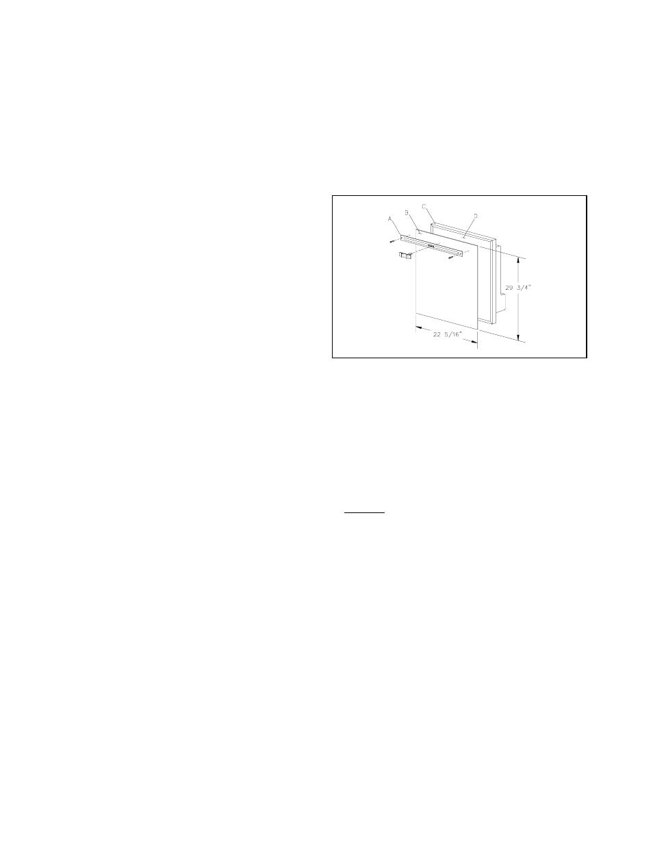
Installation Of Decorator Panel
Prepare the panel by cutting to size as per illustration. Use di-
mensions shown in Figure 4. The maximum panel thickness must
not exceed 3/16" (4.76mm).
1. Remove the door front decorative strip by removing the
screws and pulling the decorative strip off.
2. Insert one of the vertical sides of the panel (B) into the
groove formed by the door frame outer flange (C) and the
door front.
3. Gently flex the panel (B) so that the opposite side may be
slipped into the corresponding groove.
4. Slide the panel (B) downward so that the lower horizontal
edge fits into the bottom groove.
5. Install the door decorative strip (A) to cover the gap be-
tween the top edge of panel (B) and door frame (C). Se-
cure with screws.
CAUTION: DO NOT OVER TIGHTEN SCREWS.
Figure 4
6