Operation, Special requirements for marine installations – Thetford EV704D Series User Manual
Page 4
Further information on DC supplies can be found later in this
manual.
AC Power Connection
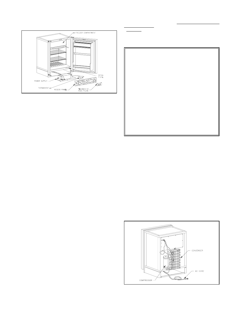
The 120 volt AC power connection is made by connecting the
refrigerator’s AC cord to a standard 120 volt grounded receptacle.
See Figure 2.
The 120 volt AC supply wires, to which the refrigerator is con-
nected, should be routed through the fuse panel or circuit breaker
that protects the vehicle when an outside power source is used.
This connection should be permanently wired in accord-
ance with existing governing codes. The use of an extension cord
is not recommended.
CAUTION:
IF AC POWER IS SUPPLIED BY AN ON-BOARD GENERATOR,
IT IS VERY IMPORTANT TO HOLD BOTH VOLTAGE AND FRE-
QUENCY WITHIN THE TOLERANCES STATED IN THE FRONT
OF THIS MANUAL
OPERATION
Power Source
As previously noted, the Norcold refrigerator can be operated on
either 12 volts DC or 120 volts AC. If both power sources are
connected simultaneously, the refrigerator will operate on 120
volts AC. A special relay disconnects the DC power. To operate
on DC power, the AC source must be disconnected, allowing the
relay to switch to 12 volts DC.
On DC operation the circuit is protected electronically for over-
current and overvoltage. Likewise on AC operation the circuit is
protected from overload conditions by a bi-metallic current limiting
device.
Temperature Control
A single thermostat controls the operation of the refrigerator on
AC or DC. It is located on the panel below the front door (See Fig.
1). The dial is marked "1" through "5". The nearer the dial is set to
"5", the colder the temperature becomes in the cabinet.
There is no need to readjust the setting of the thermostat for
dual operation. Once the desired temperature is reached, the
thermostat will control the cabinet temperature equally well on
either voltage supply.
Initial Start-up
Before operating the refrigerator for the first time, check to see
that the AC and DC supply connections are correct. If normal, the
green power indicator will be illuminated. Connect the vehicle to
the external power supply of 120 volts. Turn the switch located
next to the thermostat to the "ON" position. Turn the thermostat
dial to the number "3" setting. The unit should be operating. You
can hear the compressor sound by placing your ear next to the
refrigerator.
Allow approximately five minutes of operation and open the
freezer compartment door. Place your hand at the upper left rear
corner of the cooling plate. This is the area of the plate that will
begin cooling first. If you notice a cooling effect at this point, then
the unit is functioning properly.
Close the refrigerator door and allow the refrigerator to operate
on AC until it cycles or shuts itself off. This indicates the thermo-
stat is operating and that the refrigerator is cooling on AC opera-
tion.
Now, disconnect the AC supply and open the refrigerator door so
that the cabinet interior will warm up and allow the thermostat to
demand cooling.
As soon as the unit’s compressor begins to operate, close the
refrigerator door, allowing the unit to run. It should shut off or cycle
within 10 to 20 minutes indicating the DC operation is correct.
Special Requirements For
Marine Installations:
The DE-704D is internally wired so that the AC and DC
circuits are isolated from each other. If the positive (+12 volts)
DC input is grounded in any way (cuts in the wire insulation,
improperly insulated connections, etc.), a voltage potential
could be developed throughout the boat in which corrosion
develops on any metal parts exposed to water.
This situation may be avoided by wiring the boat so that AC
and DC grounds are common and wiring is protected per
NNMA CERTIFICATION HANDBOOK (1987). Inspect all wir-
ing to insure that insulation has not been damaged. Plastic
wire clamps are recommended.
To obtain more information on corrosion, a good reference
is:
BOAT AND YACHT CORROSION CONTROL
by Yacht Corrosion Consultants, Inc.
2368 Eastman Ave. #6, Ventura, Ca. 93003.
Figure 2
Figure 1
4