Symtech CVA3 EZ User Manual
Page 5
5
Move glide plate up and down the mast through its full motion, by
depressing handle.
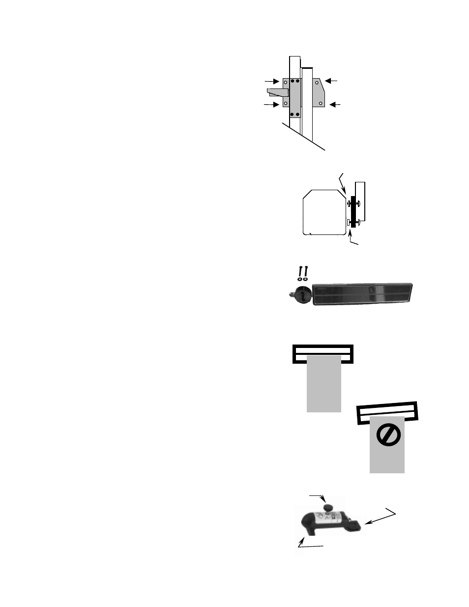
2.3 OPTICAL ALIGNMENT HEAD
Remove optical alignment head from shipping carton.
Inspect for any damage that may have occurred during
shipment i.e. lens, case, etc..
Attach optical alignment head to the mast glide plate by
aligning mounting holes of glide plate with the holes in
the optical head. Insert _ x 20 x _ allen head machine
screws through glide plate, place a _ x _ nylon spacers
on each upper screws, place a _ x
1
/
2
nylon spacers on
each lower screws, attach optical head and tighten
securely.
Remove protective paper covering from viewing window
on top of optical head.
Move optical head through the full range of movement to
assure of smooth operation.
2.4 VEHICLE ALIGNMENT MIRROR
Vehicle alignment mirror assembly is
enclosed
in the accessories box.
NOTE: Mount mirror assembly so that unit is
located directly over the optical head.
Insert 2, _ x 20 x 1
1
/
2
screws (Small Parts
Package) into mirror calibration block and attach all
to top of mast.
DO NOT TIGHTEN. Tighten to a tension that
allows for sufficient movement during calibration.
After calibration has been performed tighten
securely.
NOTE: Sighting unit must be calibrated to the optical head prior
to alignment of headlamps.
2.5 SIGHTING UNIT CALIBRATION
Calibration of sighting unit must be performed prior to alignment of
headlamps.
Raise optical head of CVA 3
EZ
to the approximate center of travel
of mast.
Turn the sighting unit until you can see the reflection of the front
edge of the optical head. Line on mirror should line up with the
front edge of the optical head.
If line does not line up with the front edge of optical head, rotate
mirror assembly until line is parallel with front of optical head.
Tighten screws.
It is important that periodical checking of calibration of the vehicle
alignment mirror be performed, to assure customer satisfaction.
2.6 FLOOR SLOPE LASER
The floor slope laser assembly is factory calibrated, DO
NOT turn the level adjustment set screw which is at the
back of laser assembly.
The laser is used for floor slope measurement only. Remove
laser after floor slope measurements have been recorded
Glide
Plate
_ x _ Black
Nylon Spacers
Optical
Head
IN
Calibration
OUT of
Calibration
Optical
Head
On / Off
Knob
Level Adjuster
Set Screw
Fixture
Placement Pin
_ x 20 x _
Allen head
Optical
Head
_ x _ White
Nylon Spacers