Ring Communications DNA100 User Manual
Page 6
April 2012 Digital Network Adapter DNA100
INSTALLATION
Each DNA100 in a system can be individually powered from a fuse in the CB901 or a local power supply
operating off 24V regulated DC.
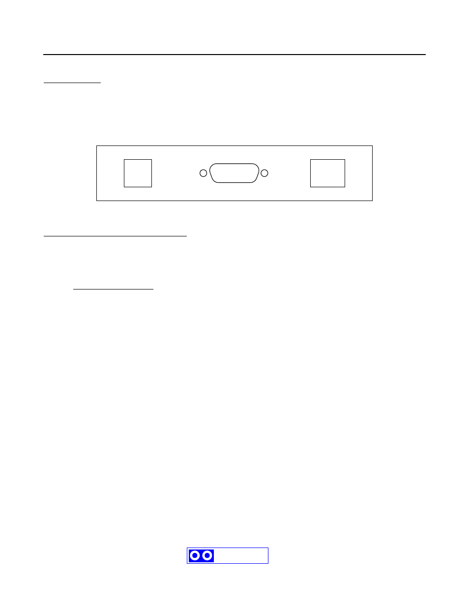
J1 - 8 pin (RJ45) Network connections :
Two modular jacks are provided at the rear of the DNA100. See Figure C1. Use modular cables with straight
through pin configuration only! An 8-pin (RJ45) modular jack (KB171) and cord (BF640A) are required for
connection to the network.
PIN# - DESIGNATION
1 - No connection.
2 - +12 VDC power input
3 - Data + (positive)
4 - No connection.
5 - No connection.
6 - Data - (negative)
7 - -12 VDC power input
8 - External Alarm.
The maximum total network length is 7000 feet. A unshielded twisted pair cable should be used for the data pair
(24 or 22 AWG).
2
123456
12345678
J3
J2
J1
RS422
RS232
RS485
Ring-Master