5 backlight, Ktam3874/pitx user's guide, 1 power connector backlight pins – Kontron KTAM3874-pITX User Manual
Page 19
KTD-S0051-D Page
15
Graphics Processing Subsystem
KTAM3874/pITX User's Guide
5.5
Backlight
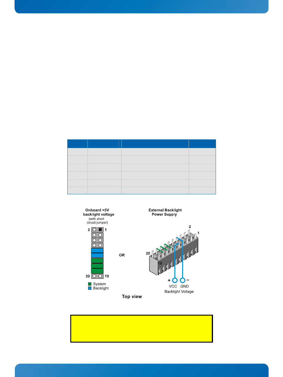
Backlight is available through the connector J1800. The backlight voltage can be supplied from the on-
board +5V voltage if you set one or two short circuit jumper on connector J2100. For backlight voltages
differing from +5V use pin 9 and/or 11 on connector J2100 to supply the backlight (pins 7 and 8 represent
the associated ground, identical with board ground).
With a GPIO line (GP3[14]) you can switch the brightness signal between an analog (0 - 5.0V) and a PWM
signal.
5.5.1
Power Connector Backlight Pins
The following table is an extract of the J2100 connector overview. For further details about pin 1 see
chapter 'Default Power Configuration'.
Pin
Signal
Description
Type
9
VDD
1)
External backlight voltage input
PWR IN
10
VCC5
1)
Onboard power +5V
PWR
11
VDD
1)
External backlight voltage input
PWR IN
12
VCC5
1)
Onboard power +5V
PWR
7
GND
Backlight ground
PWR
8
GND
Backlight ground
PWR
CAUTION!
If you use an external backlight power supply do not forget the three
system links (pin 13 to 18) otherwise the board does not start.