Clocks, 1 clock assignment, Backplane clock assignment – Kontron CPCI Backplane User Manual
Page 19: Cpci backplane general
CPCI Backplane
General
ID 24229, Rev. 03
© 2005 Kontron Modular Computers GmbH
Page 5
2422
9.03.UG.VC.051007/14565
3
P R E L I M I N A R Y
•
IPMI/IPMB functionality
•
Flexible grounding option
•
Fan connector
•
Drive connector
•
Power LED Connector
•
PS-ON Connector
•
Reset function connector
2.
Clocks
2.1 Clock Assignment
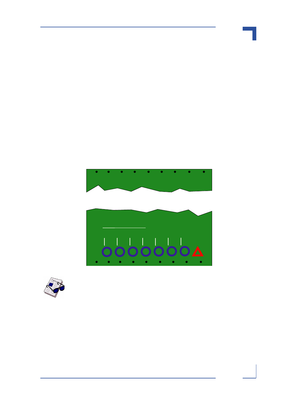
The system slot provides clock signals for all the PCI peripherals in the system including de-
vices on the system slot board. Each peripheral slot is provided with only one clock signal.
Clock numbering assignment begins with the slot adjacent to the system slot and is numbered
starting from 0.
Figure 2:
Backplane Clock Assignment
Note ...
The CompactPCI Specification, 2.0, R2.1 requires only five discrete PCI clocks
to be available. Backplanes and system controller boards which support R2.1
but not R3.0 do not necessarily support seven PCI clocks. For this reason, it is
necessary to refer to the documentation provided with such backplanes or sys-
tem slot boards to determine the actual clock output and numbering for the sys-
tem.
Clock numbering:
5
6
4
3
2
1
0