Jp12, Jp11, Cpci backplane pd18: cp6-bp4-pb-rio – Kontron CP6-BP4-PB-RIO User Manual
Page 9
CPCI Backplane
PD18: CP6-BP4-PB-RIO
RID 24229 PD18, Rev. 01
© 2003 PEP Modular Computers GmbH
Page 9
5.5
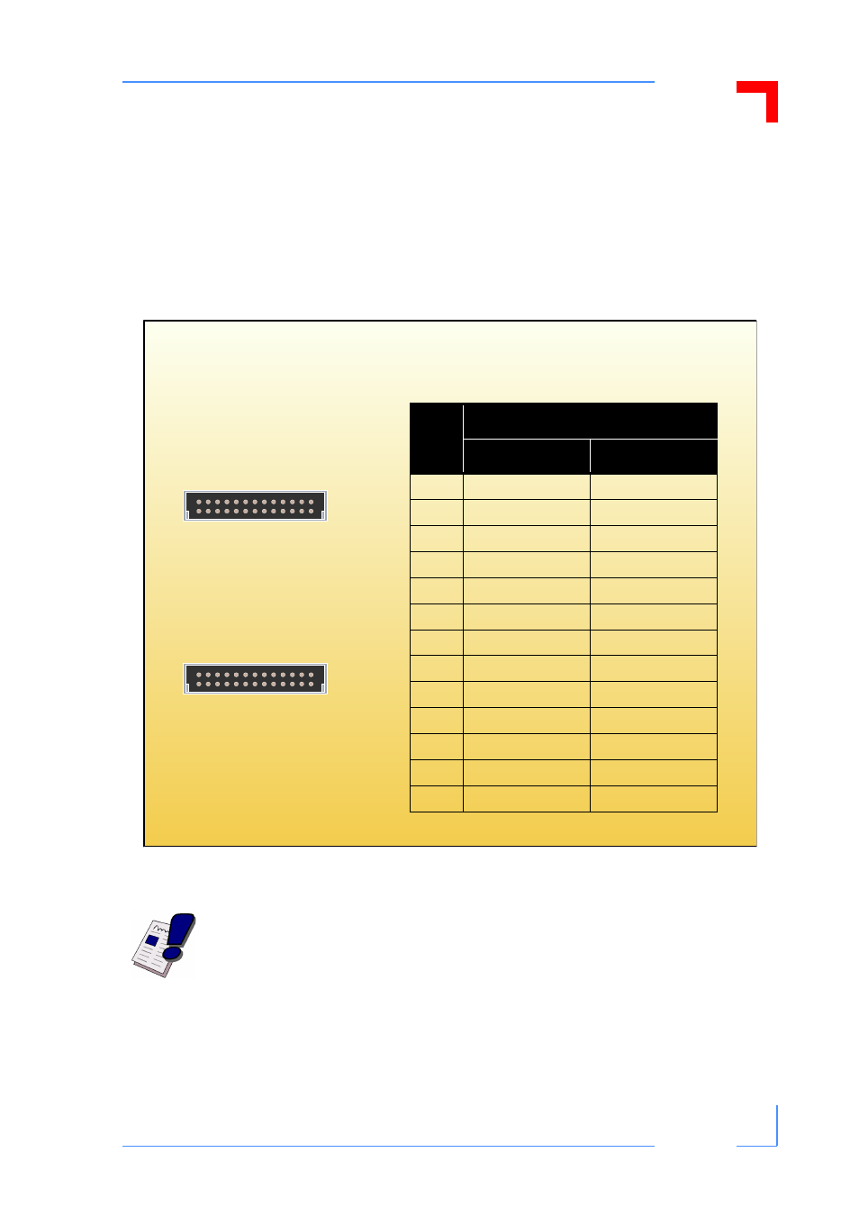
System Monitor and Control Connectors JP11 and JP12
This backplane is provided with two connectors for system monitor and control signal interfac-
ing to external devices. Both are 26-contact, male, double pin-row connectors, and have the
same signal pinout configuration. The system management bus (IPMB0), the power supply
monitor and control signals, and push button reset (PRST#) signal are all implemented on
these connectors.
Figure 6: Orientation and Pinout of the SMC Connectors JP11 and JP12
Note...
The signal pinout assignment is a function of the power supply actually utilized
with this backplane. Refer to the corresponding power supply documentation for
the applicable signal pinout.
1
13
b
a
JP12
1
13
b
a
JP11
Table 6: Pinout of SMC Connectors
JP11 and JP12
Pin
Function
Pin Row A
Pin Row B
1
IMPB0_SCL
GND
2
IMPB0_SDA
IMPB0_PWR
3
N/C
GND
4
N/C
GND
5
N/C
GND
6
INH#
GND
7
FAL#
DEG#
8
PRST#
GND
9
GND
V1 SENSE (+5V)
10
V2 SENSE (+3.3V)
SENSE RTN
11
V3 SENSE (+12V)
GND
12
V1 SHARE (+5V)
V2 SHARE (+3.3V)
13
V3 SHARE (+12V)
GND