3 system management connectors jp19 and jp20, 4 msd connector, Pd18: cp6-bp4-pb-rio cpci backplane – Kontron CP6-BP4-PB-RIO User Manual
Page 8
PD18: CP6-BP4-PB-RIO
CPCI Backplane
Page 8
© 2003 PEP Modular Computers GmbH
RID 24229 PD18, Rev. 01
5.3
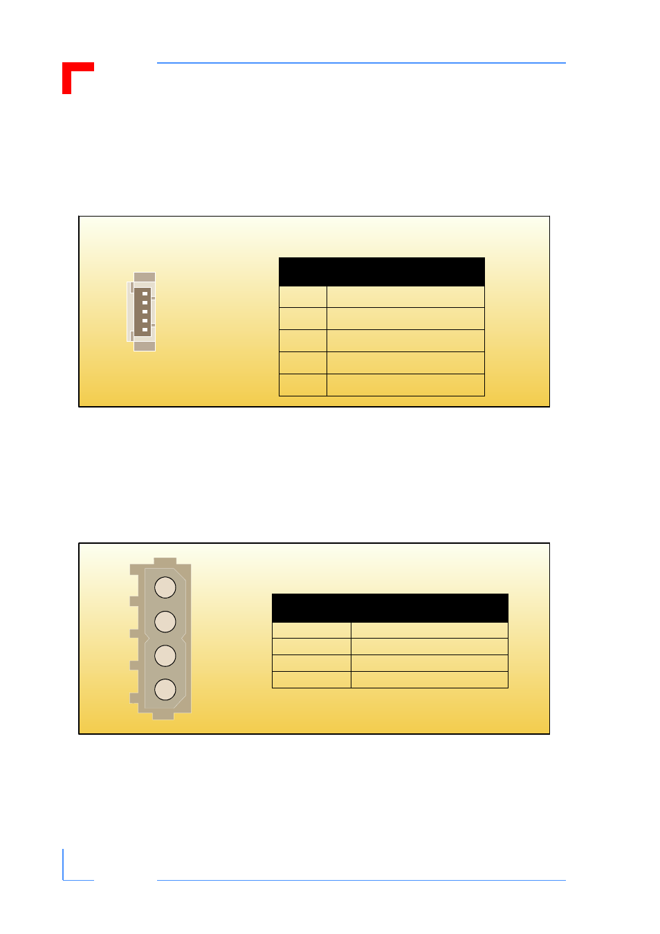
System Management Connectors JP19 and JP20
Two five-contact male system management bus (IPMB0/1) connectors, JP19/20, can be
optionally provided for external interfacing to this bus.
Figure 4: Orientation and Pinout of the IMPB0/1 Connectors JP19/20
5.4
MSD Connector
One 4-pole Molex male connector, JP4,
can be optionally equipped on the backplane for the
connection of mass storage devices (drives) to the +5V/+12V power supply of the bus.
Figure 5: Orientation and Pinout of Connector JP4
1
5
Table 4: Pinout of IMPB0/1
Connectors JP19/20
Pin
Function
1
IMPB0_SCL / IMPB1_SCL
2
GND
3
IMPB0_SDA / IMPB1_SDA
4
IMPB_PWR / V
5
SMB_Alert *
* JP20 only
1
2
3
4
Table 5: Pinout of Connector JP4
Pin
Function
1
+12V
2
GND
3
GND
4
+5V
- CP3003-SA uEFI BIOS (72 pages)
- CP3003-SA (36 pages)
- CP3002 (38 pages)
- CP3002-RC uEFI (64 pages)
- CP-RIO3-05 (42 pages)
- CP3002-RC (30 pages)
- CP342 (52 pages)
- CP930 (46 pages)
- CP932 (52 pages)
- CP346 (72 pages)
- CP384 (66 pages)
- CP383 (74 pages)
- CP382 (58 pages)
- CP381 (60 pages)
- CP372 (64 pages)
- CP371 (60 pages)
- CP-RIO3-04S (38 pages)
- CP390 (36 pages)
- CPS3410 (9 pages)
- CPS3402 (9 pages)
- CPS3105 (9 pages)
- CPS3101 (9 pages)
- CPS3003-SA (19 pages)
- PB-SIO4 (34 pages)
- PB-SIO4A (34 pages)
- PB-DOUT8 (34 pages)
- VMOD-2 (82 pages)
- VSBC-32 (110 pages)
- VM42 (62 pages)
- Bootstrap Loader (24 pages)
- VMP1 with Netbootloader (120 pages)
- VMP1 (106 pages)
- NetBootLoader (86 pages)
- VMP2 (142 pages)
- VMP3 (154 pages)
- CP-RIO6-923 (32 pages)
- CP-RIO6-923-F (32 pages)
- CP-RIO6-001 (28 pages)
- CP-RIO6-001-HD-VGA (46 pages)
- CP-RIO6-M (20 pages)
- CP-RIO6-B (28 pages)
- CP6925 (42 pages)
- CP6002 uEFI BIOS (76 pages)
- CP6002 IPMI (40 pages)
- CP6002 (42 pages)