3 floppy (from etx® onboard super i/o controller), 4 feature connector, Floppy (from etx® onboard super i/o controller) – Kontron ETX-Starterkit User Manual
Page 10: Feature connector
4 Connector pinout
Kontron Short Description
ETX® Eval-Board
10
4.1.3
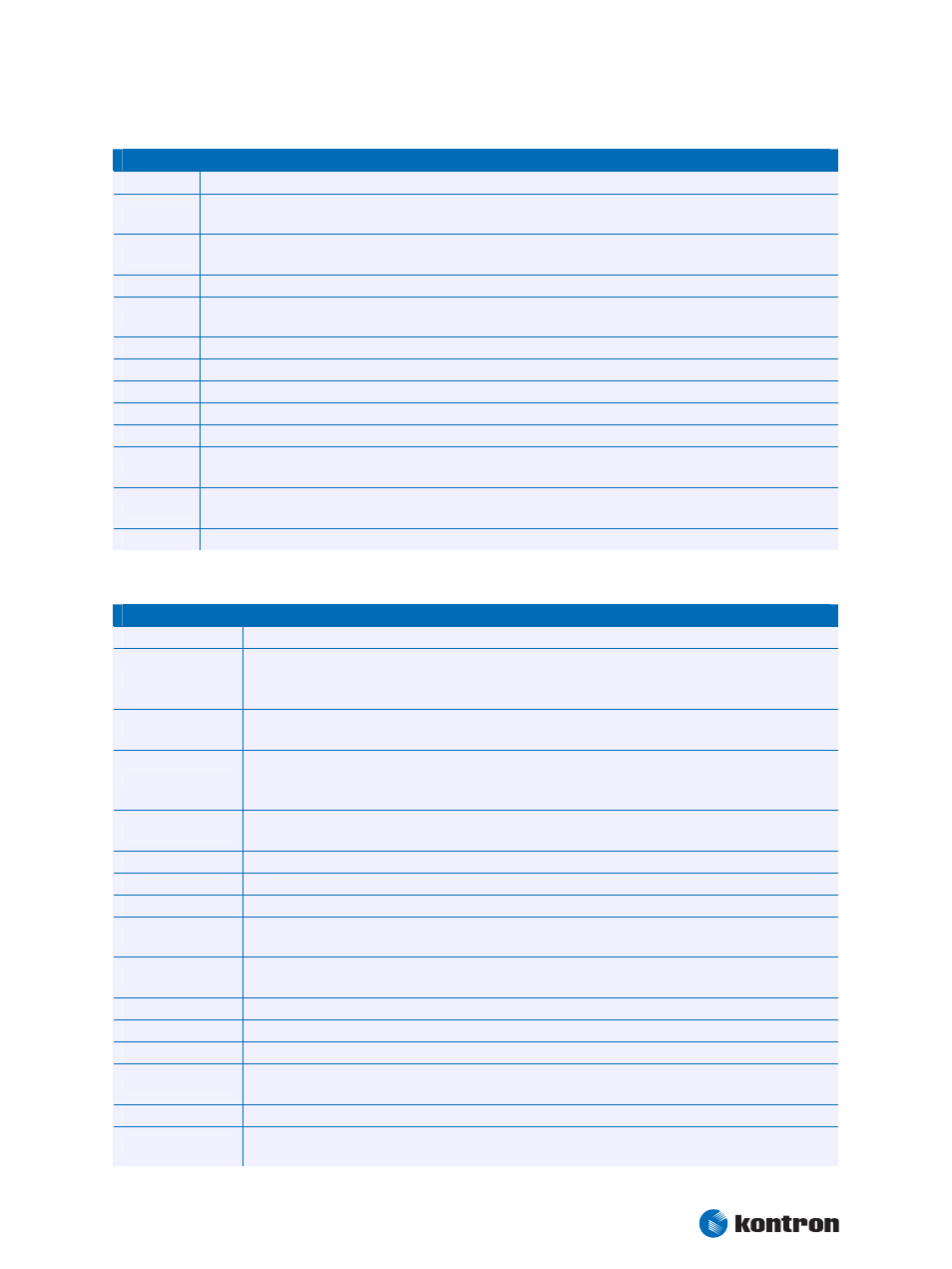
Floppy (from ETX® onboard Super I/O controller)
Floppy (from ETX® onboard Super I/O controller)
DENSEL
Indicates whether a low (250/300Kb/s) or high (500/1000Kbs) data rate has been selected.
INDEX#
This active-low Schmitt Trigger input signal is asserted by the disk drive when the diskette index hole is
sensed.
TRK0#
This active-low Schmitt Trigger input signal is asserted by the disk drive when the head is positioned over the
outermost track.
WP#
This active-low Schmitt Trigger input signal is asserted by the disk drive when a disk is write-protected.
RDATA#
The active-low, raw-data read signal from the disk drive. Each falling edge represents a flux transition of the
encoded data.
DSKCHG#
This active-low input signal is asserted by the disk drive when the drive door has been opened.
DRV
This signal selects the floppy drive.
MOT
This active-low output activates the disk drive motor.
HDSEL#
This active-low output determines which disk drive head is active. Low = Head 0. High (open) = Head 1.
DIR#
This active-low output determines the direction of head movement (low = step-in, high = step-out).
STEP#
This active-low output signal is pulsed at a software-programmable rate to move the head during a seek
operation.
WDATA#
This active-low output is a write pre-compensated serial data stream to be written onto the selected disk
drive. Each falling edge causes a flux change on the media.
WGATE#
This active-low output enables the write circuitry of the selected disk drive.
4.1.4
Feature connector
Feature connector
VCC_UL
+5V UL-protected with inductor (220nH, 800mA)
GPE2#
General-purpose power management event input 2. May be driven low by external circuitry to signal
an external power management event. Within the ETX® module, this pin is commonly connected to
the chipset’s RING# input.
BATLOW#
Battery low input. May be driven low by external circuitry to signal that the system battery is low, or
may be used to signal some other external power management event.
GPE1#
General-purpose power management event input 1. May be driven low by external circuitry to signal
an external power management event. Within the ETX® module, this pin is commonly connected to
the chipset’s LID# input.
RSMRST#
Resume Reset input. This input may be driven low by external circuitry in order to reset the power
management logic on the ETX® module.
EXTSMI
System management interrupt input. May be driven low by external circuitry to initiate an SMI.
SERIRQ
Serial interrupt request. This pin is used to support the serial interrupt protocol.
GPCS#
Reserved. Do not connect to this pin.
I2CLK, I2DAT
Clock and data line of I2C-Bus. Switched I/O-lines with approximate 10kHz. Do not use as multi
master. Intended for I2C and other simple I/O-devices.
SMBALRT#
System Management Bus Alert input. May be driven low by SMB devices in order to signal an event on
the SM Bus.
SMBDATA, SMBCLK Clock and data line of SM-Bus. For future use. Do not use today.
EXT_PRG
Reserved. Do not connect to this pin.
ROMKBCS#
Reserved. Do not connect to this pin.
BATT
3V backup cell input. BATT should be connected to a 3V backup cell for RTC operation and storage
register non-volatility in the absence of system power. (VBATT = 2.4 – 3.3V)
KBINH
Keyboard Inhibit.
PWGIN
High active input for the ETX®-PC indicates that power from the power supply is ready. It can also be
used as low active reset input signal.