2 front panel, Front panel - 7, Am4020 introduction – Kontron AM4020 User Manual
Page 25
AM4020
Introduction
ID 1036-1863, Rev. 3.0
Page 1 - 7
P R E L I M I N A R Y
1.4.2
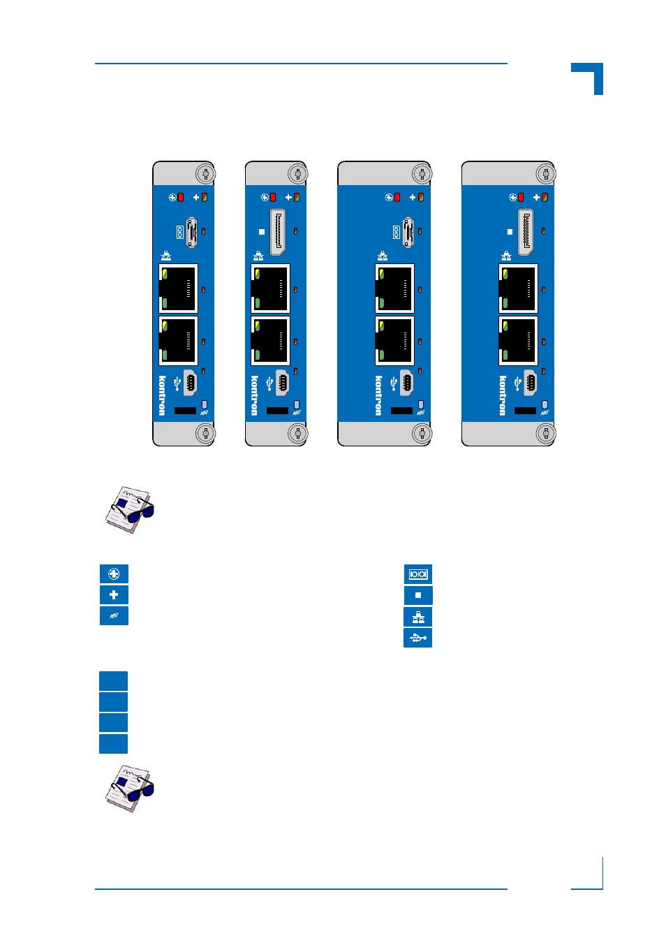
Front Panel
Figure 1-2:
AM4020 Front Panel Versions
0
1
2
3
AM4020
GbE D
GbE C
AM4020
GbE D
GbE C
AM4020
GbE D
GbE C
AM4020
GbE D
GbE C
0
1
2
3
0
1
2
3
0
1
2
3
Mid-size AM4020
with COM Port
Mid-size AM4020
with DisplayPort
Full-size AM4020
with COM Port
Full-size AM4020
with DisplayPort
D
P
D
P
For further information on the LEDs used on the AM4020, refer to section 2.10.1, “Front Panel
LEDs”.
Note ...
The AM4020 is also available without retaining screws on the front panel.
Module Management LEDs
Connectors
• LED1 (red):
Out-of-Service LED
• LED2 (red/green):
Health LED
• HS LED (blue):
Hot Swap LED
• Serial Connector
• DisplayPort Connector
• Gigabit Ethernet Connector
• USB Connector
User-Specific LEDs
• ULED3 (red/green): AMC Ethernet port A link signal status, AMC port 0 (green) + POST
• ULED2 (red/green): AMC Ethernet port B link signal status, AMC port 1 (green) + POST
• ULED1 (red/green): SATA channels active (green) + POST
• ULED0 (red/green): POST
Note ...
If the ULED 0..3 are lit red during boot-up, a failure is indicated before the uEFI
BIOS has started. For further information, please contact Kontron.
D
P
3
2
1
0